
SEQUENTIAL LOGIC -II
E N D
Presentation Transcript
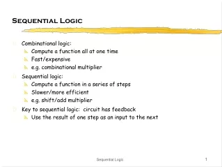
Latch versus Register • Latch stores data when clock is low • Register stores data when clock rises D Q D Q Clk Clk Clk Clk D D Q Q
CLK D Q D D Clk CLK Clk D Q Writing into a Static Latch Use the clock as a decoupling signal, that distinguishes between the transparent and opaque states Forcing the state (can implement as NMOS-only)
Q 0 Q 1 D 1 D 0 CLK Mux-Based Latches Negative latch (transparent when CLK= 0) Positive latch (transparent when CLK= 1) CLK
Mux-Based Latch (can implement as NMOS-only)
Mux-Based Latch (NMOS Only) NMOS only Non-overlapping clocks
Master-Slave (Edge-Triggered) Register Two opposite latches trigger on edge Also called master-slave latch pair
Master-Slave Register Multiplexer-based latch pair
Clk-Q Delay 2.5 CLK 1.5 D t c q(lh) t c q(hl) Volts Q 0.5 2 0.5 0 0.5 1 1.5 2 2.5 time, nsec
Setup Time – I2 – T2 = 0.20 nsec = 0.21 nsec
Avoiding Clock Overlap X CLK CLK Q A D B CLK CLK (a) Schematic diagram CLK CLK (b) Overlapping clock pairs
Static SR Latches ─Cross-Coupled Pairs NOR-based set-reset Overpowering the Feedback Loop
Cross-Coupled NAND Added clock Cross-coupled NANDs This is not used in datapaths any more,but is a basic building memory cell
Sizing Issues Output voltage dependence on transistor width Transient response
Storage Mechanisms Dynamic (charge-based) Static CLK D Q CLK
Setup/Hold Time Illustrations Circuit before clock arrival (Setup-1 case)
Setup/Hold Time Illustrations Circuit before clock arrival (Setup-1 case)
Setup/Hold Time Illustrations Circuit before clock arrival (Setup-1 case)
Setup/Hold Time Illustrations Circuit before clock arrival (Setup-1 case)
Setup/Hold Time Illustrations Circuit before clock arrival (Setup-1 case)
Setup/Hold Time Illustrations Hold-1 case 0
Setup/Hold Time Illustrations Hold-1 case 0
Setup/Hold Time Illustrations Hold-1 case 0
Setup/Hold Time Illustrations Hold-1 case 0
Setup/Hold Time Illustrations Hold-1 case 0
Other Latches/Registers: C2MOS “Keepers” can be added to make circuit pseudo-static
Insensitive to Clock-Overlap V V V V DD DD DD DD M M M M 2 6 2 6 M M 0 0 4 8 X X D Q D Q M M 1 1 3 7 M M M M 1 5 1 5 (a) (0-0) overlap (b) (1-1) overlap
Other Latches/Registers: TSPC Positive latch (transparent when CLK= 1) Negative latch (transparent when CLK= 0)
Including Logic in TSPC Example: logic inside the latch AND latch
Pulse-Triggered LatchesAn Alternative Approach Ways to design an edge-triggered sequential cell: Master-Slave Latches Pulse-Triggered Latch L1 L2 L Data Data D Q D Q D Q Clk Clk Clk Clk Clk
Pulsed Latches Hybrid Latch – Flip-flop (HLFF), AMD K-6 and K-7 :
Sense-Amplifier Based Registers Sense-amplifier-based flip-flop, DEC Alpha 21264, StrongARM 110 • First stage is a sense amplifier, precharged to high, when Clk = 0 • After rising edge of clock sense amplifier generates the pulse S or R • The pulse is captured S-R latch • Cross-coupled NAND has different delays of rising and falling edges
Pipelining Pipelined Reference
Non-Bistable Sequential Circuits─Schmitt Trigger • VTC with hysteresis • Restores signal slopes
CMOS Schmitt Trigger Moves switching threshold of the first inverter
Schmitt Trigger Simulated VTC 2.5 2.5 2.0 2.0 V 1.5 1.5 M + (V) (V) x X 1.0 1.0 V V V M - k = 1 k = 3 k = 2 0.5 0.5 k = 4 0.0 0.0 0.0 0.5 1.0 1.5 2.0 2.5 0.0 0.5 1.0 1.5 2.0 2.5 V (V) V (V) in in Voltage-transfer characteristics with hysteresis. The effect of varying the ratio of the PMOS device M . The width is k * 0.5 m. m 4