Download
1 / 19
810 likes | 3.62k Vues
FUNDAMENTALS OF GAS TURBINE CONTROL. P2M FTUI September 2008. INTRODUCTION.

E N D
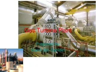
FUNDAMENTALS OF GAS TURBINE CONTROL P2M FTUI September 2008
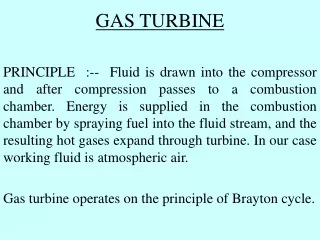
INTRODUCTION • Control System is designed to fulfill all gas turbine control requirements. Theseinclude control of liquid, gas or both fuels inaccordance with the requirements of the speed,load control under part-load conditions, temperature control under maximum capabilityconditions or during startup conditions. In addition, inlet guide vanes and water or steam injection are controlled to meet emissions and operating requirements.basic system.
INTRODUCTION • If emissions control uses Dry Low NOxtechniques, fuel staging and combustion mode are controlled by the system, which also monitors the process.Sequencing of the auxiliaries to allow fully automated startup, shutdown and cool down are alsohandled by the Control System. Turbineprotection against adverse operating situationsand annunciation of abnormal conditions areincorporated into the
INSTRUMENTATION • VIBRATION MEASUREMENT • PRESSURE MEASUREMENT • TEMPERATURE MEASUREMENT
Typical Instrumentation (MinimumRequirements) 1. Accelerometer a.At machine inlet bearing case, vertical b.At the machine discharge bearing case, vertical c.At machine inlet bearing case, axial 2. Process pressure a.Pressure drop across filter b.Pressure at compressor and turbine inlet c.Pressure at compressor and turbine discharge
Typical Instrumentation (MinimumRequirements 3. Process temperature a.Temperature at compressor and turbine inlet b.Temperature at compressor and turbine discharge 4. Machine speed a.Machine speed of all shafts 5. Thrust-bearing temperature a.Thermocouples or resistance temperature elements embedded in front and rear thrustbearing
VIBRATION MEASUREMENT • Machine vibration is monitored using: • Displacement probes • Velocity pickup detectors • Accelerometers (measurement of acceleration)
PRESSURE MEASUREMENT • Pressure transducers to be used the locations ofpressure and temperature probes in a typical gas turbine
TEMPERATURE MEASUREMENT • Temperature detectors such as • thermocouples (used for high-temperature measurement) • resistive thermal detectors (RTDs)
TEMPERATURE MEASUREMENT • Turbine exhaust temperature • Redundant RTDs are embedded in the babbitt (white metal) of the bearing to monitorthe oil temperature in the bearings • The compressor inlet and discharge temperatures are measured to evaluate the compressor performance
Thermocouples • Thermocouples provide transducers used for measuring temperatures from 330 to5000°F (201 to 2760°C). Figure 17.3 shows the useful range of each type of thermocouples. They operate by producing a voltage proportional to the temperature differencebetween two junctions of dissimilar metals. Thermocouples measure this voltage to deter-mine the temperature difference. The temperature at one of the junctions is known. Thus,the temperature at the other junction can be determined. Since they produce a voltage, thereis no need for an external power supply
Resistive Thermal Detectors • Resistive thermal detectors (RTDs) determine the temperature by measuring the change inresistance of an element due to a change in temperature. Platinum is normally used in RTDsdue to its mechanical and electrical stability. Platinum RTDs are used for measuring temperatures from 454 to 1832°F (270 to 1000°C). The RTD requires an electrical currentsource to operate. Its accuracy is within ±0.02°F (± 0.01°C)
CONTROL SYSTEM FUNCTIONS • Gas Turbine Control System performs many functions including fuel,air and emissions control; sequencing of turbinefuel and auxiliaries for startup, shutdown and cooldown; synchronization and voltage match-ing of the generator and system; monitoring ofall turbine, control and auxiliary functions; andprotection against unsafe and adverse operatingconditions.
CONTROL SYSTEM • The control system of a gas turbine performs the following functions • Provides speed and temperature control in the machine • Control the unit during normal operation • Provide protection to the gas turbine • Perform start-up and shutdown sequence of events
Speed Control • Magnetic transducers measure the speed of the shaft at a toothed wheel mounted on theshaft. The transducers provide an output in the form of AC voltage having a frequency proportional to the rotational speed of the shaft. A frequency-to-voltage converter is used toprovide a voltage proportional to the speed. This measured value of the speed is then com-pared to the desired value of the speed (speed setpoint). The difference between these twovalues is called the error.If there is an error, the control system will adjust the opening ofthe fuel valve to eliminate it. It relies on a proportional-integral-derivative (PID) algorithm(mathematical expression) to eliminate the error within minimal time and without instabilities (oscillations in the speed).
Temperature Control • A series of thermocouples mounted around the periphery at the exhaust of the turbine pro-vides an input to the control system. They are normally made from iron-constantan orchromel-alumel fully enclosed in magnesium oxide sheaths to prevent erosion. Two thermocouples are frequently mounted for each combustion can. The redundancy improves thereliability of the control system. The output of the thermocouples is generally averaged.The control system compares this measured value of the turbine exhaust temperature withthe desired value of setpoint.The difference between these values is called the temperatureerror.If the temperature error is different from zero, the control system will adjust theopening of the fuel valve to eliminate it. It relies also on PID algorithm to eliminate theerror within minimal time and without instabilities.
Protective Systems • The protective systems provide protection during the following events: • Overspeed • Overtemperature • Vibration • Loss of flame • Loss of lubrication
START-UP SEQUENCE • The gas turbine control system performs the start-up sequence. It consists of ensuring thatall subsystems of the gas turbine perform satisfactorily, and the turbine rotor temperaturedoes not increase too rapidly or overheat during start-up. The control system is designed tostart the unit remotely, accelerate it to operating speed, synchronize it automatically withthe grid, and increase the load to the desired setting.
OPERATION ANDMAINTENANCE • The operator interface is comprised of a VGAcolor graphics monitor (or LCD), keyboard and printer.The functions available on the operator inter-face as follows