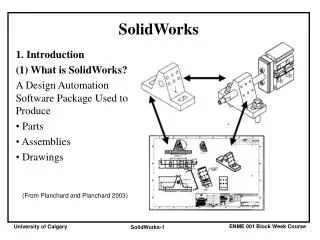
EdgeCAM Solid Machinist for SolidWorks
EdgeCAM Solid Machinist for SolidWorks. EdgeCAM Solid Machinist for SolidWorks. Turning Production Milling Surface Machining. EdgeCAM Turning. This presentation shows a SolidWorks part on a sub-spindle, twin turret, mill/turn lathe.


EdgeCAM Solid Machinist for SolidWorks
E N D
Presentation Transcript
EdgeCAM Solid Machinist for SolidWorks Turning Production Milling Surface Machining
EdgeCAM Turning This presentation shows a SolidWorks part on a sub-spindle, twin turret, mill/turn lathe.
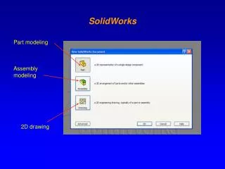
Use the EdgeCAM launch button within SolidWorks to load the part into EdgeCAM.
Using Feature Finder, EdgeCAM finds the turned features. Note: The feature profiles generated are of the maximum turned sweep and not just a simple section.
Notice that an associative copy of the part, with features, has been transferred to the sub-spindle.
Open the Instruction Browser. This machine has an upper and lower tool turret. These are shown side by side in the browser. The screen has also been split into two and zoomed into the component areas to be machined.
Face the part in the main spindle. Notice the Time Line. This will expand as new toolpaths are added.
Now using the lower turret, face the back of the part in the sub-spindle.
The profile of the part can now be milled using C axis milling.
Add synchronization to ensure that subsequent events do not take place until both the main and sub-spindle have finished what they are doing. Spaces are added to the browser to provide clarity.
Dock the sub-spindle with the main spindle to pick up the component.
EdgeCAM is constantly looking at the original SolidWorks model and automatically reports if it has been updated.
With the new part automatically loaded onto both the main and sub-spindles, Feature Finder looks at the new model and identifies changed, deleted and new features relative to the original model. Changed features are easy to identify through bold text in the Feature Browser.
It can be seen that the turned profile has been changed, making the existing toolpaths unusable.
Updating the toolpaths to the new profile is easily done by clicking on the regenerate button.
The Time Line shows all the activities on both spindles and both turrets.
The machining of the part can now be verified using EdgeCAM Simulator.
EdgeCAM Production Milling This presentation shows a component part loaded onto a fixture and rotary table within SolidWorks. The assembly is loaded directly into EdgeCAM and the part machined.
The part and its stock model can be assembled on to a fixture within SolidWorks.
The assembly can be loaded into EdgeCAM using the EdgeCAM launch button.
With the assembly loaded into EdgeCAM, Feature Finder identifies machineable features: pockets, bosses and holes.
Here are the features found for the current coordinate plane.
The roughing process uses the casting as the stock boundary.
Features can be machined by selecting them from the Feature Browser or selecting them from the solid model.
Selecting the tapped hole features provides the option to perform a hole machining operation.
This operation will perform the spot drill, deep drill and tapping processes within a single click.
Utilizing the hole sizes from SolidWorks, EdgeCAM identifies the correct tools from the ToolStore, with appropriate feeds and speeds.
These toolpaths can now be repeated for the other four faces.
These toolpaths can then be rationalized to minimize cycle time.
Feature Finder automatically identifies the features that have changed.
The roughing cycle is updated to the new model and stock casting. The hole process is also updated for the two new tapped holes on all five faces.
EdgeCAM Surface Machining This presentation shows different EdgeCAM toolpaths used in the manufacture of components with sculptured solids and surfaces.