Download

1 / 22
230 likes | 469 Vues
RoadRailer Air Brake Fault Localization. ECE 480 Design Team 8 Tia Twigg Marcelo de Castro Saurav Shrestha Abdulaziz Najm Dilo Benjamin. Introduction:. RoadRailer system: Bi-modal transportation Trailers Bogies Air ride system lifts trailer so bogie can roll under it

E N D
RoadRailer Air Brake Fault Localization ECE 480 Design Team 8 Tia Twigg Marcelo de Castro Saurav Shrestha Abdulaziz Najm Dilo Benjamin
Introduction: RoadRailer system: • Bi-modal transportation • Trailers • Bogies • Air ride system lifts trailer so bogie can roll under it • Tires lift to clear rails
Introduction: Assembling the train: • Trailers and bogies are connected to form the train • The glad-hands connect the air brake lines from the trailers to the bogies
Project Goals: Hardware: • Develop a system to detect leaks or obstructions in air brake hoses Software: • Develop back-end software to compare incoming data with established baseline
Design Specifications: Objectives: • Air tight hose connector • Accuracy within ±0.1 psi • Transmit and receive signals from multiple sensors • Display data from all sensors on one screen Constraints: • Durable and weather proof • Independent power source • Easy to install, maintain and operate
Design Solutions: Hardware • Glad-hand rose adaptor • Air tight • Installed in a non-destructive way into the existing system using glad-hands
Design Solutions Sensor • Independent power source • Pressure range 100 psi with ±0.1 psi accuracy • Operating temperature : -40°C to 85°C • Wireless range 1.5 km Base Station • Easy to install and operate • ZigBee protocols
Design Solutions Sensor • Pressure range 100 psi with 0.1 psi accuracy • Operating temperature: -20 °F to 120 °F • Independent power source • Battery life 2 months • Wireless range 1.5km • Cost Base Station • ZigBee protocols • secure data connections • Collision avoidance • Support for multiple network topologies such as mesh networks
LOOKING BACK AT PROJECT GOALS • Solution • Remote Antenna • improve line-of-sight and signal strength • Wireless communication between sensors
Pressure Sensor 1 Test Application • Provides a packet of information for one pressure sensor in real-time. • Packet of information includes primary pressure, battery voltage, strength of received signal and module temperature. • User role: Connect receiver to the computer; • use X-CTU software to enable wireless communication • enter sensor serial number and number of counts in PS1 Test Application.
Multi Test Application • Collects same packet of information as that of PS1 Test Application in real time. • Used to collect information from multiple sensors. • User role: PS1 Test Application user role + enter sampling period (seconds)
Back-end Processing Application • Designed and added a back-end processing application in Multi-Test Application and PS1 Test Application. • User Role: Multi Test 1/PS1 Application Role + enter a range for normal pressure value. • PS1 Back-end Processing: Separate plots for each sensors. User will set limit for each of the sensors. • Multi Test Back-end Processing: Application will make individual graphs for each sensor’s pressure in one plot. • Both back-end processing application will flash message in real-time if the incoming pressure reading is outside the range.
Suggestions for future design improvements Better functionality for purchased sensors Practical tests of device on the actual pressure system Finding alternative solutions for the wireless range Further develop Backend Process
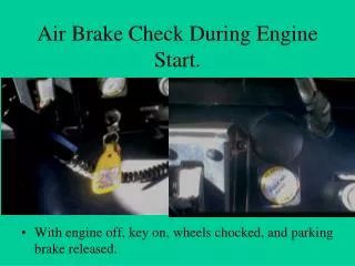
Tests Notes and Assumptions Clamp Hose 50 psi Not instantaneous Reading Setup Nitrogen Tank 5 Glad hand connectors 2 pressure sensors Pressure gauge 1 leaky hose
Tests Procedure Simulate the actual system Connect via glad hands Create restriction Turn on the pressure tank Results Restricted side pressurized slower Leak affected the restricted side Once the tank was turned off, restricted side dropped pressure faster due to leak
Demonstration Pressurized with no restriction/ leaks • Pressurized with restriction/ leak
Conclusion Designed an adapter for the glad-hand connectors Pressure sensors installed in the adapter will transmit pressure information wirelessly Sensor operates in harsh environments – from rain to desert storms Developed a back-end software to display out of rage pressure readings Tested the device in the laboratory to determine functionality