Download
1 / 34
360 likes | 668 Vues
Design and Analysis of Fins with Realistic Boundary Conditions. P M V Subbarao Associate Professor Mechanical Engineering Department IIT Delhi. Design for Maximum Benefits for a given Cost…. Linear Second order ODE with Constant Coefficients. At the base of the fin:.

E N D
Design and Analysis of Fins with Realistic Boundary Conditions P M V Subbarao Associate Professor Mechanical Engineering Department IIT Delhi Design for Maximum Benefits for a given Cost….
Linear Second order ODE with Constant Coefficients At the base of the fin:
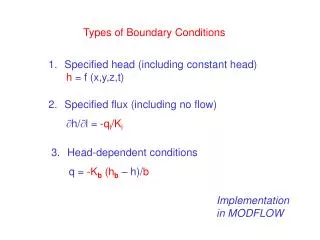
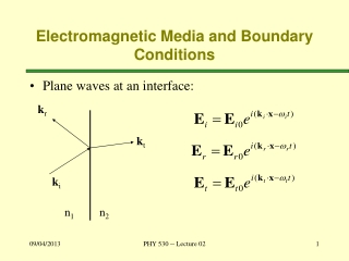
Convection or Radiation Most Realistic Boundary Condition Convection or Equivalent convection at tip: Corrected adiabatic tip:
Strip Fin : Adiabatic Tip The boundary condition are: Using these gives: and The foregoing shows that:
The heat flow through the fin at any location x is: And at x=b (heat entering fin base): For a strip fin:
Cost – Benefit Analysis of Fins • The benefit of a fin is defined as effectiveness of a fin. • An ideal fin will have highest value of effectiveness. • An ideal fin is the one whose temperature is equal to temperature of the surface. • This is possible only if the thermal conductivity of fin material is infinitely high. • The effectiveness of an actual fin material is always lower than an ideal fin. • The relative performance of a given fin is defined as efficiency of a fin. • Provision of fins on a surface requires more material and hence more capital cost. • A judicial decision is necessary to select correct factors of fin design. • Best fin design should have higher benefits with a lower amount of material.
Effectiveness of A Fin : Strip Fin • The fin effectiveness,efin , is defined as the ratio of the heat dissipation with fin to the heat dissipation without a fin.
Efficiency of Strip Fin The fin efficiency, h, is defined as the ratio of the actual heat dissipation to the ideal heat dissipation if the entire fin were to operate at the base temperature excess
For infinitely long strip fin: For Adiabatic strip fin:
Longitudinal Fin of Rectangular Profile: Adiabatic tip • Temperature Excess Profile • Heat Dissipated • = Heat Entering Base • Fin Efficiency
Strip Fin of Least Material • The heat flux is not constant throughout the fin surface area. • It decreases as some function of distance from the fin base. • Two models are possible: • For a constant heat flux, the cross-section of the fin must also decrease as some function of distance from the base. • Schmidt reasoned that the problem reduced to the determination of a fin width function, d(x), that would yield minimum profile area.
Longitudinal Fin of Least Material Constant Heat Flux Model Consider With A a function of x. Then For a constant heat flux (with k a constant by assumption): and which is a linear temperature excess profile. The practical feasibility of this solution depends on ease of manufacturing.
Strip Fin of Least Material : OPTIMUM SHAPES • Least profile area for a given rate of heat transfer can be modified as maximum rate of heat transfer for a given profile area Ap • For a Longitudinal fin of Rectangular Cross Section with L = 1: ( L=1) , let With Hence
Optimum Shapes : Strip Fin Find the best shape where and get Solving iteratively gives bR=1.4192 Find the optimum shape for a given Ap
Performance of Optimum Profiles : Strip Fin(L=1) Heat dissipated Optimum fin width (mb=1.4192)
Performance of Optimum Profiles Optimum shape for a given qb & qb And solve for Ap with [ tanh (1.4192) = 0.8894 ]
Selection of Fin Material Rectangular Profile: Consider three popular materials: Steel Aluminum Copper 7249 2704 8895 43.3 202.5 389.4
Selection of Fin Material For a given length, fin mass is proportional to Ap. Apis inversely proportional to thermal conductivity. For given h, qb, and qb:
Comparison of Longitudinal Fin profile area varies as the cube of To double the heat flow, you use two fins or make one fin eight times as large. There is a virtue in using short stubby fins.
L qb x b x=b x=a=0 LONGITUDINAL FIN OF TRIANGULAR PROFILE The differential equation for temperature excess :
L qb x b x=b x=a=0 LONGITUDINAL FIN OF TRIANGULAR PROFILE The differential equation for temperature excess is a form of Bessel’s equation:
Triangular Fin : Adiabatic Tip The particular solution for is: The fin heat dissipation is: The fin efficiency is:
Optimum Shapes : Triangular Fin L=1 With This makes
Optimum Shapes Iterative solving yields bT=2.6188 and
Comparison of Longitudinal Fins Rectangular Profile: Triangular Profile: For the same material, surrounding conditions and which is basically the user’s design requirement. Triangular profile requires only about 68.8% as much metal as rectangular profile.
Comparison of Longitudinal Fin In both fins, profile area varies as the cube of To double the heat flow, you use two fins or make one fin eight times as large. There is a virtue in using short stubby fins.