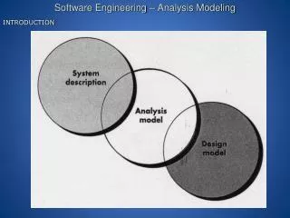

Information Flow Modeling: Analysis, Modeling, and Function Modeling
E N D
Presentation Transcript
Function Modeling & Information Flow • Information is transformed as it flows through a computer-based system. The system accepts input in a variety of forms; applies hardware, software, and human elements to transform it; and produces output in a variety of forms • Structured analysis began as an information flow modeling technique. • A rectangle is used to represent an external entity (software, hardware, a person) • A circle (sometimes called a bubble) represents a process or transform that is applied to data (or control) and changes it in some way.
Function Modeling & Information Flow • An arrow represents one or more data items (data objects) and it should be labeled. • The double line represents a data store—stored information that is used by the software. • First data flow model (sometimes called a level 0 DFD or context diagram) represents the entire system. • It provides incremental detail with each subsequent level.
Creating a Data Flow Model • It enables software engineer to develop models of the information domain and functional domain at the same time. • Data flow diagram may be used to represent a system or software at any level of abstraction • As DFD is refined into greater levels of detail, the analyst performs an implicit functional decomposition of the system. • As DFD refinement results in corresponding refinement of data as it moves through the processes that represent the application
DFD Guidelines • Depict the system as single bubble in level 0. • Primary input and output should be carefully noted • Refine by isolating candidate processes and their associated, data objects and data stores • All arrows and bubbles should be labeled with meaningful names. • Information flow continuity must be maintained from level to level. • One bubble at a time should be refined.
Data flow models • A level 0 DFD, also called a fundamental system model or a context model, represents the entire software element as a single bubble with input and output data indicated by incoming and outgoing arrows. • Level 0 DFD refinement into level 1 DFD with all relevant processes to the system. • Level 1 DFD each processes can be refined into level 2 DFD. • Refinement of DFD continues until each bubble performs a simple function.
Control flow model • Application which contains collection of classes are dependent on event rather than data, produce control information rather than reports or displays. • Such application require the use of control flow modeling in addition to data flow modeling.
Guideline for control flow • List all processes that are performed by the software. • List all the interrupt conditions. • List all activities that are performed by operator or actor. • List all data conditions. • Review all the “Control items” as possible for control flow inputs / outputs. • Describe the behavior of a system by identifying its states; identify how each state is reached; define the transitions between states. • Focus on possible omission – a very common error in specifying control
Control Specification (CSPEC) • CSPEC represent the behavior of the system in two different ways. • It contains a state diagram – sequential specification of behavior. • It also contain program activation table – combinatorial specification of behavior. • By reviewing the state diagram, a software engineer can determine the behavior of the system and can discover whether there are “holes” in specified behavior. • CSPEC describe the behavior of the system, but it gives us no information about the inner working of the processes that activated result.
Process Specification (PSPEC) • Used to describe all flow model processes that appear at the final level of refinement. • It include narrative text, a program design language (PDL) description of the process algorithm, mathematical equations, tables, diagrams or charts. • By providing a PSPEC to accompany each bubble in the flow model, the software engineer creates a “mini-spec” that can serve as guide for design of the software component that will implement the process.