Nuclear Power Plant Orientation
360 likes | 660 Vues
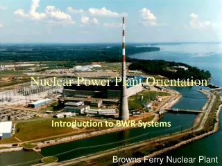
Nuclear Power Plant Orientation. Introduction to BWR Systems. Browns Ferry Nuclear Plant. Introduction. During this phase of the training we will discuss the basic operation of a Boiling Water Reactor (BWR) Plant, including:

Nuclear Power Plant Orientation
E N D
Presentation Transcript
Nuclear Power Plant Orientation Introduction to BWR Systems Browns Ferry Nuclear Plant
Introduction • During this phase of the training we will discuss the basic operation of a Boiling Water Reactor (BWR) Plant, including: • the major design concepts of the Browns Ferry BWR-4 and its Mark I containment • the importance of nuclear safety. • We will also discuss several of the systems associated with BFN’s operation.
Enabling Objectives • Identify the major components and flowpaths in the steam cycle. • Recognize the functions of water in a BWR • Recognize the functions of the control rods in a BWR • Recognize the capability and purpose of nuclear instrumentation
Enabling Objectives • Identify alternate sources of emergency cooling water to the reactor vessel • Relate major concepts employed in containment design • Identify inherent safety features of a BWR • Compare advantages and disadvantages of a BWR to that of a PWR
HPT001.014D Rev. 0 Page 5 of 34 HPT001.014D Rev. 0 Page 5 of 34 $ Tennessee River
BWR Design • Selected by GE due to its inherent advantages in control and design simplicity. • Single loop system; steam and associated secondary systems are radioactive. • Operating pressure is approximately half that of a PWR at 1,000 psi. • Capacity of units two and three is ~1,100 Mwe each.
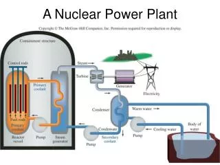
BWR Internal Flow • Feedwater enters downcomer. • Recirculation loops provide forced circulation. • Moisture removed by separators and dryers. • Steam exits steam dome.
BWR Internal Flow HPT001.014D Rev. 0 Page 8 of 34 Core 8
Recirculation System Flow Path HPT001.014D Rev. 0 Page 9 of 34 Jet Pump Risers Recirc Pump Suction Ring Header Recirc Pump Motor 9
HPT001.014D Rev. 0 Page 10 of 34 Steam Dryer installed in Reactor Pressure Vessel 10
HPT001.014D Rev. 0 Page 11 of 34 Steam Dryer stored in Equipment Pit 11
HPT001.014D Rev. 0 Page 12 of 34 Fuel Transfer Canal 12
Plant Layout • The entire Reactor Coolant System (RCS) and other primary support systems are located within containment (the drywell) and reactor buildings. • Main Steam, Condensate and Feedwater (all radioactive) are housed within the turbine building. • The reactor is operated remotely from the control building.
Main Steam System • Steam generated by the reactor is admitted to four main steam lines. • One high pressure and three low pressure turbines convert thermody- namic energy into mechanical energy to drive the main generator. • Safety objective is to prevent overpressurization of the nuclear system.
Main Steam System Flow Path HPT001.014D Rev. 0 Page 15 of 34 RPV To HP and LP Turbines 15
Condensate and Feedwater Systems • Once the steam has passed through the high and low pressure turbines, it must be condensed and then pumped back to the reactor so that the cycle can be repeated. • These systems will collect, pre-heat, and purify feedwater prior to its return to the reactor plant.
Condensate System Flow Path B C A HPT001.014D Rev. 0 Page 17 of 34 LP FW Heaters B A C A B C 17
Feedwater System Flow Path HPT001.014D Rev. 0 Page 18 of 34 HP FW Heaters Reactor Pressure Vessel RPV Primary Containment Reactor Feed Pumps 18
Fuel Cell • Currently, Framatome is the supplier of fuel for BFN. • Four fuel bundles per cell. • 764 bundles per reactor.
HPT001.014D Rev. 0 Page 20 of 34 Fuel Cell Control Rod Blade 20
Control Rods • Rods contain boron as the neutron absorber. • Tubes held in cruciform array by a stainless steel sheath. • 185 control rods per reactor.
Control Rod Blade HPT001.014D Rev. 0 Page 22 of 34 22
HPT001.014D Rev. 0 Page 23 of 34 Control Rod Blades 23
Nuclear Instrumentation • Source range - 0.1 to 106 cps • Intermediate range - 104 cpsto 40% power . • Power range - 1 to 125% power. Three ranges of neutron monitoring; all in-core.
Nuclear Instrumentation HPT001.014D Rev. 0 Page 25 of 34 BOTTOM OF TOP GUIDE DETECTOR CHAMBERS LENGTH OF ACTIVE FUEL CORE SUPPORT REACTOR VESSEL IN-CORE HOUSING GUIDE TUBE REACTOR SUPPORT STRUCTURE 25
EMERGENCY CORE COOLINGSYSTEMS (ECCS) • Prevent fuel cladding fragmentation for any failure including a design basis accident. • Independent, automatically actuated cooling systems. • Function with or without off-site power. • Protection provided for extended time periods.
EMERGENCY CORE COOLINGSYSTEMS (ECCS) • High Pressure Coolant Injection (HPCI) • Low Pressure Coolant Injection (LPCI) • Core Spray • Automatic Depressurization System
Emergency Core Cooling Water Sources HPT001.014D Rev. 0 Page 28 of 34 Condensate Storage Tanks ~2,000,000 gal Normal Systems Reactor CONDENSATE FEEDWATER CONTROL ROD DRIVE Emergency Systems HIGH PRESSURE COOLANT INJECTIONCORE SPRAYLOW PRESSURE COOLANT INJECTION Torus ~950,000 gal Tennessee River RHR SVC WATER FIRE PROTECTION 28
Primary and Secondary Containment • Primary Containment consists of the Drywell and Suppression Pool (Torus). • Secondary Containment consists of the Reactor Building. • Designed to contain the energy and prevent significant fission product release in the event of a loss of coolant accident.
Containment Design • Structural Strength - steel structure with reinforced concrete able to withstand internal pressure. • Pressure Suppression - large pool of water in position to condense steam released from LOCA. • Designed to contain the energy and prevent significant fission product release in the event of a loss of coolant accident.
Torus HPT001.014D Rev. 0 Page 31 of 34 Primary and Secondary Containment Drywell 31
Advantages of BWRs • Single loop eliminates steam generator • Bottom entry control rods reduce refueling outage time/cost; also provide adequate shutdown margin during refueling. • Lower operating pressure lowers cost to obtain safety margin against piping rupture. • Design simplifies accident response.
Disadvantages of BWRs • More radiation/contamination areas; increased cost associated with radwaste. • Piping susceptible to intergranular stress corrosion cracking (IGSCC). • Off-gas issues (e.g. - H2 gas presents explosion potential, low levels of radioactive noble gases are continuously released).
Summary • A Boiling Water Reactor plant is comprised of many different and complex systems, all of which support the overall goal of safely producing electricity. • The design challenge of a BWR is to incorporate all the criteria of power generation and safety in non-conflicting ways in order to meet the load demand of the public and satisfy the requirements set forth by the Nuclear Regulatory Commission (NRC).