Download
1 / 51
510 likes | 535 Vues
Explore the design considerations for continuous-wave operation in cryomodules, including heat removal, helium vessel design, magnetic field management, and heat transport. Learn about thermal efficiency and constraints to ensure optimal performance.

E N D
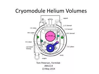
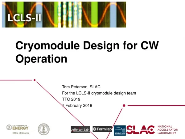
Cryomodule Design for CW Operation Tom Peterson, SLAC For the LCLS-II cryomodule design team TTC 2019 7 February 2019
Cryomodule design for CW operation • Primary issues for CW operation from the point of view of thermal design are: • 2 Kelvin heat removal • Helium vessel design • Helium liquid and vapor flow • Piping design • Maintaining high cavity Q0 • Low imposed magnetic fields, excellent magnetic “hygiene” • Magnetic flux expulsion which can involve special cool-down requirements Peterson, CW Cryomodule Design, 7 Feb 2019
Helium vessel style The first TESLA helium vessel concept was for a large CEBAF- style helium vessel. Difficulties: 1. Huge helium inventory in a TESLA-sized system. 2. Mechanical tuning efficiency with tuner outside of helium vessel. Peterson, CW Cryomodule Design, 7 Feb 2019
2 K heat in first few cryomodules of LCLS-II From LCLScryoHeat-18Sep2015.xlsx Peterson, CW Cryomodule Design, 7 Feb 2019
A look at the thermodynamics of RF cavity cooling -- subcoolingin a liquid bath Saturated liquid (in equilibrium with vapor at its surface) has a higher pressure below the surface by virtue of the weight of the liquid. This pressure provides the possibility for a slightly elevated temperature below the surface without boiling and/or some subcoolingbelow the vapor pressure at that higher pressure. The pressure under a head of liquid is Peterson, CW Cryomodule Design, 7 Feb 2019
Heat transport vertically to surface The pressure head of liquid helium and behavior of 2-phase helium around 2 Kelvin tell us that helium saturation temperature increases by about 1.5 mK/cm of depth. Substituting 0.0015 K/cm into equations for helium II heat transport results in 1.2 W/cm2 heat flux vertically to the surface of the helium II. This heat flux is essentially independent of depth for the depths of 10’s of cm typical of RF helium vessels. I use 1 W/cm2 as a limitfor sizing a conduit for heat transport to the surface of a saturated helium II bath. The following slide illustrates the effect of a longer horizontal heat flow path for a given vertical head of helium. Peterson, CW Cryomodule Design, 7 Feb 2019
Heat transport considerationsFigure from CW OPERATION OF SUPERCONDUCTING TESLA CAVITIES, W. Anders, J. Knobloch, O. Kugeler, A. Neumann, BESSY, Berlin, Germany Limit for Helium II heat transport in a saturated bath is about 0.5 W/sq.cm to 1.4 W/sq.cm depending on flow path relative to liquid surface Peterson, LCLS-II Cryogenics, 11 February 2019
Helium II heat transport within the helium vessel Peterson, CW Cryomodule Design, 7 Feb 2019
Chimney size, step up in diameter at Ti-SS transition • Maximum heat about 24 Watts. • Various constraints limit nozzle into • helium vessel to 60.2 mm ID • Increased heat transport margin from • 25% to 50% Peterson, 3.9 GHz Cryomodule Design, 26 May 2016
Chimney heatload limit Nominal operation Max. operation Maximum heat load capacity is calculated ~ 36.2 W (50% margin) Heater (28 W) operated in parallel to cavity (12 W): ~40 W heatload capacity LCLS-II 3.9 GHz CM Delta FDR | S. Aderhold: Design Verification (Cavities), Jan 29 2019 Heat load capacity limited by chimney size Limited area on helium vessel -> stepwise diameter increase
Analysis of helium II heat flow and emergency venting flow through internal magnetic shielding verify adequate total flow area via the multiple small and three large holes. • Documented in “Helium II Heat Flow from 3.9 GHz Helium Vessel,” LCLSII-4.5-EN-0851-R0 Peterson, 3.9 GHz Cryomodule Heat, 30 Jan 2017
3.9 GHz thermal design summary Peterson, 3.9 GHz Cryomodule Heat, 30 Jan 2017 • LCLS-II 3.9 GHz cryomodule heat loads may be larger than for the 1.3 GHz cryomodule • Likely around 110 W per cryomodule as opposed to 90 W for 1.3 GHz • Smaller helium vessel with higher heat load means higher heat flux • The helium vessel, internal magnetic shield, and chimney connection to the 2-phase pipe have all been carefully analyzed and designed for the anticipated worst-case heat loads • The 3.9 GHz cryomodule cryogenic design includes some advantages over 1.3 GHz cryomodules • Venting of the 2-phase pipe to the 300 mm pipe at the uphill end of the cryomodule, with liquid/vapor supply also near the uphill end about a meter away, will provide lower vapor velocities • A shorter cryomodule means liquid elevation differences from end to end will be less than for 1.3 GHz
2-pipe 2 Kelvin vapor system XFEL or ILC cryomodule, a modified TESLA-type Peterson, CW Cryomodule Design, 7 Feb 2019
Cryomodule Pipe Sizing Criteria • Heat transport from cavity to 2-phase pipe • 1 Watt/cm2 is a conservative rule for a vertical pipe (less heat flux with horizontal lengths) • Two phase pipe size • 5 meters/sec vapor “speed limit” over liquid (CERN / Grenoble studies) • Not smaller than nozzle from helium vessel • Gas return pipe (also serves as the support pipe in TESLA-style CM) • Pressure drop < 10% of total pressure in normal operation • Support structure considerations • Loss of vacuum venting P < cold MAWP at cavity • Path includes nozzle from helium vessel, 2-phase pipe, may include gas return pipe, and any external vent lines Peterson, CW Cryomodule Design, 7 Feb 2019
High Q0 requirement drives some new design features Peterson, CW Cryomodule Design, 7 Feb 2019 • We assume Q0 = 2.7E10 in our design for 1.3 GHz • Magnetic shielding to keep < 5 mGauss • New features necessary such as active external coils • High rate of cool-down through superconducting transition • VTS results were best with much as 2 – 3 Kelvin/minute through 9.2 K transition temperature • Key is high delta-T within Nb to “sweep out” magnetic flux • For fast cool-down, option to cool one cryomodule or a few cryomodulesat a time • Create a closed-ended warm-up/cool-down manifold (line H) for each cryomodule so as to provide a cool-down/warm-up valve on each cryomodule • Design for 30 grams/sec of 5 Kelvin helium flow into cryomodule during cavity transition through 9.2 K • Retain original plan for uniform cooling of bimetallic joints • Note: closing line H has liquid helium management advantages, also
Cool-down below 80 K (LCLS-II-EN-4.5-0479) Peterson, CW Cryomodule Design, 7 Feb 2019 • Fast cool-down may start at 80 K or colder • “Fast” means 2 – 3 K/minute (“slow” < 0.5 K/minute) (reference: Anna Grassellino’s presentations) • Since thermal shield is ~35 K – 55 K, we assume 40 K delta-T at 3 K/minute, which implies 13 minutes for transition from thermal shield temperature to below the niobium 9.2 K critical temperature • Required cool-down rate can be provided with our design • “Fast” cool-down comparable to single cavity tests can be provided in a cryomodule • Cryogenic plant can provide the flow for a few cryomodules at a time • Capillary tubes and other pipes can carry the flow • Implementation . . . • We have isolated Line H (cool-down / warm-up line) for each cryomodule and provided each cryomodule with its own cool-down valve, supplied from Line A (helium supply) • Options exist for cooling many cryomodules at once, as much as an entire half-linac, using stored liquid and/or taking advantage of the relatively larger volumetric flow of cold vapor • LCLS-II-EN-4.5-0479 describes the process in detail • Time from nominally 45 K to full at 4.5 K is about 6 hours • Pump-down to 2 K is a few more hours • Total time from 300 K to 2 K is about 3 days
Illustration of fast cool-down in L2 Peterson, Cryomodule Cool-down, March 2018 • Upstream half-linac looks OK (study confirmed this) • Cool-down from the downhill end, the distribution box end, such that return flow is downhill. Cold helium naturally “drains” back downhill toward the distribution box in the 300 mm pipe. Helium strongly tends to stratify. But note that without much mixing of the cold helium with warm, the warm helium fills the pipe down to the exit level. We have this configuration only for the upstream half of the linac, L2 in particular. • Also note (thanks to Hans Quack for pointing this out): there is a blocking effect of the distribution system bypasses where the lines are elevated. Cold helium is blocked from back-flowing to the L1 and L0 cryomodules.
Temperature Plot at 300s Computational Fluid Dynamics (CFD) study by TU Dresden, results in Module 14 / Module 15 Domain A nice study by Hans Quack et al. at TU Dresden for LCLS-II fast cool-down Peterson, Cryomodule Cool-down, March 2018
Estimate of heat loads From LCLScryoHeat-18Sep2015.xlsx Summary document is Cryogenic Heat Load, LCLSII-4.5-EN-0179 Peterson, CW Cryomodule Design, 7 Feb 2019
Cryogenic plant capacity compared to our design heat loads Peterson, CW Cryomodule Design, 7 Feb 2019
2 Kelvin heat load versus average cavity Q0 Approx limit for two cryogenic plants Underlying analysis is from an older heat load estimate, but changes are less than 10%, and this illustrates the impact of Q0. Approx limit for one cryogenic plant Peterson, CW Cryomodule Design, 7 Feb 2019
Acknowledgments Peterson, CW Cryomodule Design, 7 Feb 2019 This presentation includes information from many people at Fermilab, Jlab, SLAC and others involved in cryomodule design, cryogenic distribution design, overall cryogenic system design and cryogenic systems other than LCLS-II.
Backup slides, additional information Peterson, CW Cryomodule Design, 7 Feb 2019
Design considerations • Cooling arrangement for integration into cryo system • Pipe sizes for steady-state and emergency venting • Pressure stability factors • Liquid volume, vapor volume, liquid-vapor surface area as buffers for pressure change • Evaporation or condensation rates with pressure change • Heat load estimates and uncertainty • Options for handling 4.5 K (or perhaps 5 K - 8 K) thermal intercept flow • Alignment and support stability • Thermal contraction and fixed points with closed ends Peterson, CW Cryomodule Design, 7 Feb 2019
Design upstream and downstream heat loads from Cryogenic Heat Load, LCLSII-4.5-EN-0179 Peterson, CW Cryomodule Design, 7 Feb 2019
First light upstream and downstream heat loads from Cryogenic Heat Load, LCLSII-4.5-EN-0179 Peterson, CW Cryomodule Design, 7 Feb 2019
Cryomodule pipe pressures Peterson, CW Cryomodule Design, 7 Feb 2019
LCLS-II cryomodule volumes • Fast cool-down of one cryomodule implies replacing 200 liters of helium volume as quickly as possible. • From the previous slide, we want to replace those 200 liters, starting at 40 K, with helium at ~ 5 K in 13 minutes. • Flow into the cryomodule at 15 liters/minute = 31 grams/sec liquid helium in liquefier mode. (~2 liters/min for each helium vessel) • 31 g/s sets cool-down valve size Peterson, CW Cryomodule Design, 7 Feb 2019
Cryogenic plant capacity (Cryo Plant Performance Sheet from Dana Arenius, August 5, 2014) Peterson, CW Cryomodule Design, 7 Feb 2019 • In liquefier mode (supplying 4.5 K, receiving back warm helium gas), 31 grams/sec is no problem. • However, 4 cryomodules would require 4 x 31 = 124 gr/sec, about the limit of cryogenic plant production • L3 has 20 cryomodules cooled in parallel • 31 grams/sec per cryomodule would not be available • Need to focus cooling on a few cryomodules
System cool-down process (LCLS-II-EN-4.5-0479) Peterson, CW Cryomodule Design, 7 Feb 2019 • Cool-down from 300 K to 80 K is constrained by two factors: • The need to limit forces on the three support posts due to bowing of the 300 mm Helium Gas Return Pipe (HGRP) caused by a vertical temperature gradient in the pipe • The need to avoid excessive forces and deflections due to bowing of the nominally 45 K thermal radiation shield. • The resulting constraints for cool-down (applying equally to warm-up) are described in the 1.3 GHz cryomodule FRS (LCLSII-4.5-FR-0053). • Rate limit of < 10K/hour • ΔT limit of <50K longitudinally in the HGRP, • ΔT limit of <15K radially in the HGRP. • The 35 K to 55 K circuit, nominally 5 K circuit, and 2 K circuit (including cavities and HGRP) may be cooled together, in parallel. Cooling the linac from room temperature to nominally 80 K takes about 2 days
Pressure head of helium column For helium at 4.5 K, Now, it would be good to understand the relationship of this elevated pressure below the surface to a new saturation temperature at that pressure. This new temperature, higher than the saturation temperature at the surface, tells us how much delta-T is available for heat transfer without the onset of boiling. Peterson, CW Cryomodule Design, 7 Feb 2019
Clapeyron Equation Peterson, CW Cryomodule Design, 7 Feb 2019
Delta-T available under a head of liquid helium at 4.5 K Note that 10.8 mK/meter, although a small number, implies a significant saturation temperature increase at, for example, 10 meters depth, for example down to an accelerator tunnel or experimental hall. Peterson, CW Cryomodule Design, 7 Feb 2019
Delta-T available in a column of liquid helium at 2.0 K Note that 0.14 mbar/cm or 14 mbar/meter is a significant delta-P relative to the total pressure of 30 mbar at 2.0 K. Peterson, CW Cryomodule Design, 7 Feb 2019
Helium II heat transport Peterson, CW Cryomodule Design, 7 Feb 2019
He II heat function Figure from Steven Van Sciver, Helium Cryogenics, Plenum Press, New York, 1986. Peterson, CW Cryomodule Design, 7 Feb 2019
Helium II heat transport -- near saturation pressure Peterson, CW Cryomodule Design, 7 Feb 2019
LCLS-II 1.3 GHz cryomodule flow scheme Peterson, CW Cryomodule Design, 7 Feb 2019
Cryomodule image from 3-D model Peterson, CW Cryomodule Design, 7 Feb 2019
LCLS-II cryomodule cryogenic circuits 2.4 K subcooled supply Helium gas return pipe (HGRP) Low temperature intercept supply Low temperatureintercept return High temperature shield supply High temperature shield return 2-phase pipe Warm-up/cool-down line Circuit (Line) *Line D returns 1.3 bar, 7.5 K to cryogenic plant after expansion valve Peterson, CW Cryomodule Design, 7 Feb 2019
All the dimensions, for reference Peterson, CW Cryomodule Design, 7 Feb 2019
Liquid helium management Peterson, CW Cryomodule Design, 7 Feb 2019 • High heat loads (~80 Watts per cryomodule at 2.0 K) • 0.5% tunnel slope downward in beam direction • We have followed careful design for liquid helium management • The design keeps liquid helium out of the 300 mm HGRP • Cavities are covered with liquid with plenty of allowance for liquid level control in the 2-phase pipe
Keep liquid helium out of HGRP Totally full 2-phase pipe just starts to spill into the 300 mm HGRP. But the connection from 2-phase pipe to HGRP is only at the center of the cryomodule, where the 2-phase pipe is half full. Liquid level there is 17 mm below the bottom of the 300 mm HGRP. Peterson, CW Cryomodule Design, 7 Feb 2019
But also be sure cavity is covered with liquid helium Bottom of the 2-phase pipe ID is 25 mm above the helium vessel ID top. Helium vessel is full to the top with any liquid in the 2-phase pipe. Center of the 2-phase pipe is 17 mm below the bottom of the HGRP. Peterson, CW Cryomodule Design, 7 Feb 2019
Connection from 2-phase pipe to 300 mm HGRP Connection from 2-phase pipe to 300 mm HGRP is 650 mm upstream (in beam direction) from center, up hill from center Peterson, CW Cryomodule Design, 7 Feb 2019
Downstream end with magnet and BPM Peterson, CW Cryomodule Design, 7 Feb 2019
Downstream end showing magnet current leads Peterson, CW Cryomodule Design, 7 Feb 2019
Another view, from the aisle side Peterson, CW Cryomodule Design, 7 Feb 2019
Upstream end, receives the sliding vacuum bellows Peterson, CW Cryomodule Design, 7 Feb 2019