SPL Short Cryomodule Design
460 likes | 649 Vues
SPL Short Cryomodule Design. Mock-up status, pressure relief devices and vacuum vessel mechanical calculations. P. Azevedo (CERN-TE/MSC) SPL Internal Meeting, 07/12/2012. Summary. Overview of cavity supporting system Status of supporting system mock-up

SPL Short Cryomodule Design
E N D
Presentation Transcript
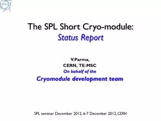
SPL Short Cryomodule Design Mock-up status, pressure relief devices and vacuum vessel mechanical calculations P. Azevedo (CERN-TE/MSC) SPL Internal Meeting, 07/12/2012
Summary • Overview of cavity supporting system • Status of supporting system mock-up • Pressure relief devices: introduction • Bursting discs for LHe 2K volume • Vacuum vessel relief plate • Lower protection levels (for process and vacuum volumes) • Vacuum vessel mechanical calculations SPL Internal Meeting, 07/12/2012
1. Overview of cavity supporting system Supporting concept: Power coupler double tube as support • The power coupler double tube acts as vertical support and longitudinal positioner • The design is simplified • Better thermal performance - less heat conduction paths from room temperature SPL Internal Meeting, 07/12/2012
1. Overview of cavity supporting system Alignment tolerances 1.2 mm isanacceptablevalue for thecavitiesmisalignment (3σ)* *Summary of the 4th SPL SCM Working Group meeting held on 26/06/2012; R.Bonomi SPL Internal Meeting, 07/12/2012 Cryomodule tolerances, V. Parma
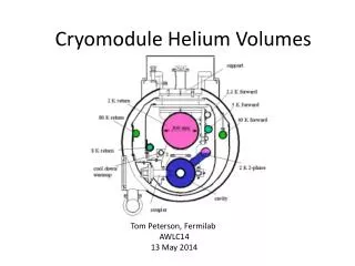
1. Overview of cavity supporting system Inter-cavity support Double tube of the power coupler Vacuum vessel Helium tank Interface with vacuum vessel SPL Internal Meeting, 07/12/2012
1. Overview of cavity supporting system Vacuum vessel / double tube interface and inter-cavity support Courtesy of P.Duthil / S.Rousselot (CNRS/IPNO) 241 mm He vessels flanges For more information on the design of these components and calculation notes concerning the supporting system, check the SPL workspace (references).. Sliding cylinder Spherical joint Deformable “triangle” SPL Internal Meeting, 07/12/2012
2. Status of supporting system mock-up Introduction Filled with LN2 Flow of GN2 • Validate the supporting and alignment concept • Test critical components of unknown behaviour, the interface with vacuum vessel and the inter-cavity support, during assembly and cool-down • Validate thermal calculations – namely the thermal model of actively cooled double • Learn about alignment survey methods and other measurements relevant for the SPL short cryomodule Mock-up developed by J-B. Deschamps, A. VandeCraen, R. Bonomi and P. Azevedo , in collaboration with different CERN groups. For more information, check the SLHiPP2 meeting presentation Mock-ups of the SPL cavity supporting system SPL Internal Meeting, 07/12/2012
2. Status of supporting system mock-up Instrumentation Scheme: Optical wire positioning monitor (stretched wire) will be installed in a second phase SPL Internal Meeting, 07/12/2012
2. Status of supporting system mock-up Courtesy of J-B. Deschamps • Design is finished – all components, cryogenic equipment and sensors have been defined / ordered • Vacuum vessel has been manufactured • Interfaces with vacuum vessel welded to double tubes (EBW) • Cold mass (LN2 tanks) ready in a couple of weeks • Assembly and instrumentation process defined • Assembly and first alignment measurements: December 2012 / January 2013 • Cool down and first cold tests: first months of 2013 SPL Internal Meeting, 07/12/2012
2. Status of supporting system mock-up Courtesyof E. Rigutto Courtesyof E. Rigutto SPL Internal Meeting, 07/12/2012
3. Pressure relief devices: Introduction Pressure / Temperature table: SPL Internal Meeting, 07/12/2012 V. Parma; SPL Pressure / Temperature Table
3. Pressure relief devices: Introduction Cryogenic Scheme: SPL Internal Meeting, 07/12/2012 O. Pirotte; SM18 PID SPL Bunker
3. Pressure relief devices: Introduction Risks overview: Work in progress SPL Internal Meeting, 07/12/2012
4. Bursting discs for LHe 2K volume Heat input due to loss of beam vacuum: different tests, different results • LHebath cooled Nbdeflector: 3 mm thick; 30 mm opening; w = 18 kW/m2 • LEP cavity: 25 mm opening; 120 g/s; w = 10 kW/m2 • 80 mm opening; 1200 g/s, w = 40 kW/m2 • XFEL cryomodule: beam pipe opening; w = 23 kW/m2 (+/- 50 % uncertainty); w = 14.2 kW/m2 (+/- 10 % uncertainty) – different heat load estimation methods • Work in progress: these values are the result of tests carried out with different equipment and in different conditions. A proper understanding of the geometrical and physical parameters is required before estimations can be made for the SPL cryomodule (cavity geometry, venting diameter, relief devices set pressure, peak pressure) Pressure protection against vacuum failures on the cryostats for LEP SC cavities; Cavallari et al; 1989 Safety aspects for LHe cryostats and LHe transport containers; Lehmann, Zahn; (1978) SPL Internal Meeting, 07/12/2012 Experimental tests of fault conditions during the cryogenic operation of a XFEL prototype cryomodule; Boeckmann et al;
4. Bursting discs for LHe 2K volume Heat input: loss of beam vacuum (no insulation) Estimate For the moment, the safety experts at CERN recommend 38 kW / m2 Table by C. Parente (DGS-SEE-XP) based on multiple sources; from calculation sheet developed by A. Henriques (DGS-SEE-XP) W. Lehmann Heat input determines mass flow: For an overpressure of 10% (Prelief = 1.55 bara): EN 13648-3 for 0.4*Pcrit< Prelief< Pcrit SPL Internal Meeting, 07/12/2012
4. Bursting discs for LHe 2K volume Heat input: loss of insulating vacuum (with MLI) Estimate For comparison purposes, an estimation of the heat input and relief mass flow in the event of loss of insulation vacuum (not the dimensioning scenario) was carried out: For an overpressure of 10% (Prelief = 1.55 bara): SPL Internal Meeting, 07/12/2012
4. Bursting discs for LHe 2K volume Relieving temperature and bursting disc(s) discharge coefficient • The saturation temperature at the relieving pressure is 4.7 K. A value of 5 K was taken as relieving temperature, based on U. Wagner’s* initial estimates (conservative) • A discharge coefficient (α)of 0.73 was taken – dependingon final design, thisvaluemaybeconservative EN ISO 4126-6 *U. Wagner; Cryogenic scheme, pipes and valves dimensions; SPL Conceptual Design Review; 04/11/2011 SPL Internal Meeting, 07/12/2012
4. Bursting discs for LHe 2K volume Results: Sizing of bursting discs Work in progress – preliminary results EN ISO 4126-6 • Formula units are not always consistent with the units presented • Kb is a correction factor for subcritical flow (function of the isentropic expansion coefficient k and pressure ratio) • C is a function of k Heat input value should be clarified before final design decisions Also affecting the design of the cryomodule:“The liquid container shall be protected against overpressure by a minimum of two relief devices in parallel, preferably of different types”* *Safety instruction IS 47: The use of cryogenics fluids ; CERN EDMS doc. 335812, by the Safety Comission SPL Internal Meeting, 07/12/2012
4. Bursting discs for LHe 2K volume Pressure drop limits and cryomodule design Work in progress – preliminary results * For 2 bursting discs, these are considered to be placed on opposite ends of the bi-phase pipe. ** Pressure drop along the bi-phase pipe: no local pressure drops considered Courtesy of P. Duthil, S. Rousselot et al, CNRS / IPNO • The pressure drop along the bi-phase pipe is significant - the total pressure drop should be limited to 3% of Ps (EN 13648-3) – 15 mbar • Local pressure drops have to be determined: since the dynamic/ velocity pressure of the discharged mass flow is 119 mbar, for an heat input of 20 kW/m2, we are limited to very small local pressure drop coefficients • An additional problem is the fact that only part of the bi-phase pipe will constitute a “free relief path” for a zero slope configuration (common LHe bath as opposed to the “roman fountain” solution for a positive slope) SPL Internal Meeting, 07/12/2012
5. Vacuum vessel relief plate Methodology – there is no “standard” method; 2 different methods were used: • A) An orifice in the 2K LHe circuit causes a discharge of LHe into the vacuum vessel (incompressible fluid). This mass flow, which depends on the orifice diameter, is the mass flow discharged by the relief plate, at subcritical flow and higher Trelief. • Highly dependent upon orifice hole andTrelief • Turns a highly transient phenomenon (LHe release into the vacuum) into a steady state process • B) Complete rupture of the 2K LHeenclosure: the vacuum vessel becomes a non-insulated cryostat. The heat load to the helium volume causes a discharge through the relief plate • The He density in the vacuum vessel is lower than the saturated vapour density at the relief pressure – mass flow calculation is not trivial For both cases, the process volume relief devices (same set pressure) are ignored – conservative assumption SPL Internal Meeting, 07/12/2012
5. Vacuum vessel relief plate Work in progress – preliminary results Method A 1st Step - incompressible flow through an orifice, into vacuum: • A is the area of the orifice • Kd is the orifice coefficient of discharge; Kd=0.62 (HSE recommendation) • P is the pressure in the process volume; • P=1.5 bar (design pressure) • Kd,RP is the coefficient of discharge of the relief plate; Kd=0.73 was taken • Y is the expansion factor for the He vapour • ARPis the area of the relief plate orifice • PV is the relief pressure (1.5 bara) • Pb is the back pressure (atmosphere) A 2nd Step - compressible and subcritical flow through vacuum vessel relief plate: DRP (mm) vsDorifice(mm) Which relief temperature? Complete rupture of C3 line bellows For the moment we can assume a 10 mm diameter as “reasonable”. This value corresponds to the complete rupture of the line C3, and to a “reasonable size for an hypothetical orifice in the bi-phase pipe bellows Complete rupture of bi-phase pipe bellows SPL Internal Meeting, 07/12/2012
5. Vacuum vessel relief plate Method B Work in progress – preliminary results Due to large vacuum vessel volume, helium density is lower than density of saturated vapour at relief pressure. Two hypothesis: 1) Vaporization of LHe mass correspondent to cryomodule volume (identical to the 2K LHe relief flow presented before) 2) Transient heat conduction to the Ghe mass filling the vacuum vessel; mass flow correspondent to density decrease due to temperature increase Calculation by R. Bonomi Which relief temperature? SPL Internal Meeting, 07/12/2012
6. Lower protection level LHe 2 K circuit Work in progress – preliminary results • Event: power failure • Heat input: static heat loads – 70 W heat load to LHe bath* *R. Bonomi, SPL Short Cryomodule Heat loads; 3rd SPL SCM WG Meeting, 22/5/2012 • Formula units are not always consistent with the units presented • Kb is a correction factor for subcritical flow (function of the isentropic expansion coefficient k and pressure ratio) • C is a function of k • Kd (Kdr=0.9 Kd) is the coefficient of discharge EN ISO 4126-1 *Tsat= 4.5 K • The mass flow and discharge area calculation follows the method used for the rupture discs (loss of beam vacuum) • Diameter is highly dependent on the coefficient of discharge (depends on the valve, and is usually lower for low set pressures) SPL Internal Meeting, 07/12/2012
6. Lower protection level Vacuum vessel • Event: temporary leak of air / air freezes immediately / leak is not detected / pressure rises during warm-up • Heat inputcalculation – appropriate method? • Relief plate (0.5 barg) behaviour at relief valve set pressure (0.3 barg, for instance)? • Possibility of using a specific relief plate design which can deal with both higher and lower protection levels (different relief pressures and discharge flows) – is being studied SPL Internal Meeting, 07/12/2012
7. Vacuum vessel mechanical calculations Introduction • Two-part vacuum vessel design carried out by CNRS/IPNO • Finished detailed design expected soon • Parallel calculations carried out at CERN From Cryomodule tolerances; V. Parma SPL Internal Meeting, 07/12/2012
7. Vacuum vessel mechanical calculations String of cavities: deflection caused by induced displacements on interfaces with vacuum vessel May 2012 • A simplified model was used to evaluate the importance of the stability of the interfaces between power couplers double tubes and vacuum vessel for the alignment of the cavities • Linear and angular displacements were applied to the double tubes flanges and the effect on the alignment of the string of cavities was estimated SPL Internal Meeting, 07/12/2012
7. Vacuum vessel mechanical calculations String of cavities: deflection caused by induced displacements on interfaces with vacuum vessel May 2012 Results: maximum allowable interfaces displacements as a function of cavity alignment tolerance: * considering the results obtained from the induced displacements on the 5th interface as valid Low angle propagation and high relative bending stiffness of inter-cavity support suggest that significant values of displacement (vertical and angular) induced on the interfaces to the vacuum vessel may compromise structural integrity of the helium vessels – although results were obtained considering a fixed connection between double tubes and vacuum vessel and an infinitely rigid vacuum vessel SPL Internal Meeting, 07/12/2012
7. Vacuum vessel mechanical calculations Stability of interfaces with double tubes during pump down • The effect of the vacuum load on the stability of the interfaces with the double tubes was studied in parallel with CNRS/IPNO (P. Duschesne) • Similar, but not identical, models, contact properties and boundary conditions were used by CERN and CNRS/IPNO September 2012 (work presented in WG meeting 6) SPL Internal Meeting, 07/12/2012 Courtesy of P. Duchesne et al ; CNRS / IPNO
7. Vacuum vessel mechanical calculations Stability of interfaces with double tubes during pump down September 2012 (work presented in WG meeting 6) Results – vertical displacement (uz) of interfaces with double tubes for vacuum load: uz [mm] Interface SPL Internal Meeting, 07/12/2012
7. Vacuum vessel mechanical calculations Mounting of the lid: effect of flat flanges shape imperfections • The effect of the shape imperfections of the two vacuum vessel connection flanges on the stability of the vacuum vessel during its closing was studied in parallel with CNRS/IPNO (P. Duchesne) • Different assumptions and calculations by CERN and CNRS/IPNO • In both cases, the closing of the vessel was not “simulated” – assumptions were made and the results are not expected to be representative • A planarity tolerance of 0.6 mm for each flange was considered Courtesy of P. Duchesne et al; CNRS / IPNO SPL Internal Meeting, 07/12/2012
7. Vacuum vessel mechanical calculations 1.2mm rattrapé par 2 vis contigües 1.2mm gap rattrapé par 4 vis à l’extrémité Mounting of the lid: effect of flat flanges shape imperfections; CNRS/IPNO approach 1.2mm 1.2mm rattrapé par 1 vis Liaisons boulonnées uniquement sur la moitié de l’enceinte CAS 1 géométrie parfaite chargement du défaut 3500mm 7000mm 242mm 242mm CAS 2 Déplacement (mm) suivant Z : 1.2mm gap rattrapé par 2 vis au centre (gauche et droit) Liaisons boulonnées uniquement sur les extrémités de l’enceinte CAS 3 Modèle: Exemple de défaut de planéité =1.2mm CAS 4 Many assumptions were made: results are not expected to be representative or definitive Elément poutre From Test cryomodule: Modélisation d’un défautgéométrique; P. Duchesne et al Connecteur rigide SPL Internal Meeting, 07/12/2012
7. Vacuum vessel mechanical calculations Mounting of the lid: effect of flat flanges shape imperfections; CERN approach • Displacements applied to bottom flange taking into account the relative stiffness of top and bottom part of vessel • Entire vessel is modelled and a perfect contact between flanges is used - this should be conservative because a more rigid connection should impose a larger flange deformation, and consequently a larger deformation of the whole bottom part of the vessel Load case 1 1.2 mm Load case 2 1.2 mm SPL Internal Meeting, 07/12/2012
7. Vacuum vessel mechanical calculations Mounting of the lid: effect of flat flanges shape imperfections; CERN approach Deformed shape: Load case 1 Load case 2 Maximum interface displacement as a function of flange displacement magnitude: Many assumptions were made: results are not expected to be representative or definitive SPL Internal Meeting, 07/12/2012
References • SPL Workspace: https://espace.cern.ch/spl-cryomodule • V. Parma; “Cryomodule tolerances” • R.Bonomi; “Summary of the 4th SPL SCM Working Group meeting held on 26/06/2012” • P. Azevedo et al; “Mock-ups of the SPL cavity supporting system”; SLHiPP2 meeting; 03/05/2012 • EN ISO 4126: Safety devices for protection against excessive pressure (parts 1,6, and 7) • EN 13648: Cryogenic vessels – Safety devices for protection against excessive pressure (part 3) • EN 13458: Cryogenic vessels – Static vacuum-insulated vessels (part 2) • U. Wagner; “Cryogenic scheme, pipes and valves dimensions”; SPL Conceptual Design Review; 04/11/2011 • R. van Weelderen; “Open Cryogenic Action Items”; 4th SPL SC WG meeting; 26/06/2012, updated 04/07/2012 • R. Bonomi; “SPL Short Cryomodule Heat loads”; 3rd SPL SCM WG Meeting, 22/5/2012 • O. Pirotte; “SM18 PID SPL Bunker” • V. Parma; “SPL Pressure / Temperature Table” • A. Henriques; "Safety Accessory Calculation Tool for Cryogenic Vessels“ • Lehmann and Zahn; “Safety aspects for LHe cryostats and LHe transport containers” (1978) • Cavallari et al; “Pressure protection against vacuum failures on the cryostats for LEP SC cavities” (1989) • Boeckmann et al; “Experimental tests of fault conditions during the cryogenic operation of a XFEL prototype cryomodule” • CERN Safety Comission; “Safety instruction IS 47: The use of cryogenics fluids”; CERN EDMS doc. 335812 • P. Azevedo; “String of cavities – deflection caused by induced displacements on interfaces with vacuum vessel” • P. Azevedo; “FE calculations of the vacuum vessel of the SPL Short Cryomodule”; 6th SPL SC WG meeting; 18/09/2012 • P. Duchesne, P. Duthil and S. Rousselot; “ Test cryomodule: Mechanicalstudies“; 6th SPL SC WG meeting; 18/09/2012 • P. Duchesne, P. Duthil and S. Rousselot; “ Test cryomodule: Modélisation d’un défaut géométrique“ SPL Internal Meeting, 07/12/2012
Static heat loads (1) RF off, cool off (2) RF off, cool on Dynamic heat loads (3) RF on, cool on (4) RF on, cool off Heat loads table - TOTAL (R.Bonomi)
Heat input table by C. Parente From A. Henriques; "Safety Accessory Calculation Tool for Cryogenic Vessels"
Local pressure drop coefficients • Examples of Minor loss coefficients for different components common in air duct distribution systems: • (http://www.engineeringtoolbox.com/minor-loss-air-ducts-fittings-d_208.html)
String of cavities: deflection caused by induced displacements on interfaces with vacuum vessel; results
String of cavities: deflection caused by induced displacements on interfaces with vacuum vessel; stress results Example (load case 2α ): Von Mises stress (MPa); model and mesh not detailed enough – this is not a stress analysis
Mounting of the lid: effect of flat flanges shape imperfections; different calculation • Opening of 5 mm between flanges (warped vessel) June 2012 For this first step load (0.6 MPa), the displacements of the interfaces are quite small. For comparison, the pressure value correspondent to 60 kN/m (reference value for 30% of O-ring deformation) is around 0.8 MPa. Displacements of interfaces with double tube (maximum absolute values)