SoLID magnet and yoke by using CLEO-II
SoLID magnet and yoke by using CLEO-II. Zhiwen Zhao 2012/07. Introduction. CLEO-II docs at https://hallaweb.jlab.org/wiki/index.php/Solid_Magnet#CLEO-II

SoLID magnet and yoke by using CLEO-II
E N D
Presentation Transcript
SoLID magnet and yokeby using CLEO-II Zhiwen Zhao 2012/07
Introduction • CLEO-II docs at https://hallaweb.jlab.org/wiki/index.php/Solid_Magnet#CLEO-II • All study were done in 2D with the Poisson Superfish program.https://hallaweb.jlab.org/wiki/index.php/Solid_Magnet#How_to_produce_the_filed_map • Eugene’s study at https://userweb.jlab.org/~gen/jlab12gev/cleo_mag/ • Based on Eugene’s study, a design fitting both PVDIS and SIDIS/Jpsi is under work.
CLEO-II • 3 section of coils, each one has two layers, • coil total 1282 turns. This includes 166,309,166 turns per layer for section upstream, middle, downstream. The result current density in two side section are 4% higher than in the middle section, • max operate current at 3266A and average current density of 1.2MA/m, this reach 1.5T field • 2 collars holding 4 coil rods • 3 layers of barrel yokes with spacers, in octagon
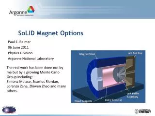
From CLEO-II to SoLID (reused parts) • Reuse coil and cryostat • Take two layers of barrel yoke and spacer, keep the upstream ends unchanged, cut the downstream ends (75cm) to our need. • Take the upstream collar unchanged, and cut the downstream collar or make a new one to satisfy the acceptance requirement. Make sure the coil rods can still be supported by two collars under axial force • All other parts of yokes are new. Endcap Donut Barrel Yoke Outer Endcap Bottom Collar Downstream The parts from CLEO-II is in the red box Spacer Spacer Barrel Yoke Inner Collar Upstream Coil Front Piece shield Endcap Nose
From CLEO-II to SoLID (new parts) • All new parts need to be customized made. • But it’s unclear if they will be made of newly machined iron ($6/lb) or we can get some unused CLEO-II iron machined (cost?) • We might try to use some “stock” parts to save machining cost. • Endcap donut: 15cm thick and has 15cm clearance to HallA floor (10 feet high) • Endcap bottom: two 15cm plates • Endcap nose: flat at back to give clearance for SIDIS forward angle EC and has slope at front to give clearance for cherenkov. • Collar downstream: 20cm thick and can be in one piece • Front Piece: 30cm thick and can move along z to adjust force on coil • shielding: a few 4cm thick plates with gaps in between. Endcap Donut Barrel Yoke Outer Endcap Bottom Collar Downstream The parts from CLEO-II is in the red box Spacer Spacer Barrel Yoke Inner Collar Upstream Coil Front Piece shield Endcap Nose
Acceptance • PVDIS physics requires opening angle from 22 - 35o • target at z= 10cm • geometry openings is 21 - 36o • clearance to endcup nose at endcup entrance (z=189cm) is 12cm for 22o and 8cm for 21o • clearance to endcup donut at forwardangleEC back (z=370cm) is 10cm for 35o and 5cm for 35.5o • beamline opening angle at endcup bottom is 3.5o • SIDIS physics requires opening angle from 8 - 24o, JPsi physics requires opening angle from 8 - 26o • target at z= -350cm • geometry openings is 7.5 – 26.3o • clearance to endcup nose at endcup entrance (z=189cm) is 15cm for 8o • clearance to endcup nose at forwardangle EC front (z=405cm) is 15cm for 8o • beamline opening angle at endcup bottom is 2o PVDIS 36o PVDIS 21o SIDIS 14.7o SIDIS 26o SIDIS 8o SIDIS 2o PVDIS 3.5o
Unit in cm, coil center at z=0 Red for change Detector Layout (SIDIS/JPsi)
Detector Layout (PVDIS) Unit in cm, coil center at z=0 Red for change
Field • The radial field Br can reach a few thousand gauss where PVDIS GEM are.
Bz along beam Eugene’s reproduction of CLEO-II • SoLIDBaBar total current 5119200A, CLEO-II total current 4187012A (current 3266A in 1282 turn). Their length is about same, so the current density is 20% less for CLEO-II • CLEO-II can still reach 1.48T similar to SoLIDBaBar • But SoLID CLEO only reaches 1.38T, due to large opening, asymmetric yoke design • could ask if CLEO-II can run higher current (unlikely)? • According to Eugene, the field integral dropped about 20% comparing to BaBar, PVDIS baffle needs to be optimized accordingly. SoLIDBaBar SoLID CLEO
field in endcup • B at nominal Cherenkovphoton sensor location are around120G and 50G • B at SIDIS forward angle EC photon sensor location is below 100G • B at PVDIS forward angle EC photon sensor location is below 500G B > 100G
saturation in Iron • Most of saturation (B>2T) is at the endcup nose, we might use iron with more field tolerance. • The physics acceptance is still 8-15cm away from the tip. • The worry is when current changes, magnetic force balance may change too. Eugene shows when current ramps up, the force change by quadratically and the force on coil doesn’t change sign. B > 2T B > 2T, zoom-in
Force on coil • Axial force on coil and cell cylinder are squeezing from both sides and it can be balanced under 10t. • could leave some net force to avoid accidental force direction change. • Preferred direction is negative so upstream collar (unchanged from CLEO-II) can take the force (?) • Moving the frontcup piece in z to adjust force (moving upstream, the positive force increase, vice verse.) with gradient 3-5t/cm (It’s very sensitive) • Radial force are on the Aluminum shell cylinder • From Eugene “If all the force goes to the shell, the azimuthal tension is about 30MPa. The yield limit of aluminum is about 100MPa (to be verified for 4°K)” 305.4 -316.5 6.3 frontcup
Force on yoke (axial force only) • 2piFz (unit in t) represents the axial force integrated over the whole part in 2pi. • positive direction in black, negative direction in Red • The opposite force meets at two locations where the endcup connects. • Some analysis of potential problems with the coil and yoke mechanical integrity should be done. • Not sure how to calculate the radial force yet. -20.3 171.2 122.9.4 -269.0 8.1 0.7 -238.4 110.2 108.6 -119.2 -79.6 0.008 0.2 165.5 0.7 0.2 38.9 0.04
Yoke weight • assume steel density is 7.9g/cm3 , weight unit is in t • material from CLEO-II 376t • new material 200t ($2.7M if assume $6/lb machined iron) • total 576t 57 7.4 195 30 3 3 17 154 21 4.4 10.4 5 6 12.5 2 2 40 2
Fringe fieldat SIDIS pol He3 target location • Multilayer of iron plates and gaps have good shielding effect • The distance between first shielding plate to the target coil is a few cm. • pol He3 holding field is 25G and we need field gradient below 100mG/cm • We need some correction coil Pol He3 target 2 Helmholtz coils Longitudinal R=75.8cm Vertical R=66.7cm
Fringe fieldat SIDIS pol He3 target location (with correction coil) • Add a pair correction coil at the same position of longitudinal coil with current -3465A and -645A • Both field and field gradient are under control • It can be tweaked further • No effect on the force on coil Pol He3 target 2 Helmholtz coils Longitudinal R=75.8cm Vertical R=66.7cm
Change from SIDIS to PVDIS (or Vice Versa) • Within coil • take out SIDIS GEM, large angle EC, collimator and front chamber of SIDIS light gas Cherenkov, then put in PVDIS GEM and baffle. • They all are need different supporting structure. • Within endcup • keep the back chamber of SIDIS light gas Cherenkov unchanged, remove heavy gas Cherenkov, remove MRPC, add PVDIS GEM, then move forward angle EC upstream and add large angle EC module to enlarge radius coverage. • light gas Cherenkov supporting structure unchanged. heavy gas Cherenkov structure removed, MRPC and Gem may share supporting structure, PVDIS EC and SIDIS EC should share supporting structure and be movable.
Change Yoke from SIDIS to PVDIS (?) • By moving 90cm long section of endcup donut and nose (flat part) away. • Advantage: • If forward angle EC photon sensor need to be outside of yoke, it’s shorter distance for fibers go through. • If Heavy gas Cherekov supporting on this part of endcup donut, it can be simply moved away. • Concerns: • the coil axial force become -1.2t comparing to -3.7tfor SIDIS, the change is only 2t but could be a problem if it changes sign. • Force on endcup part will change also. • Field mapping need to be redone.
Beamline Consideration • PVDIS beamline opening angle at endcup bottom is 3.5o • SIDIS beamline opening angle at endcup bottom is 2o • Moller electrons for PVDIS, SIDIS He3 target and JPsi • For SIDIS proton target setup, there are • synchrotron radiation around 3o due to chicane before target (need shielding) • Bremsstrahlung around 1.5o due to 5T target field. (within beamline) • Moller electrons are bended around 4o (need shielding)
Summary • Overall we have a preliminary design • Baffle needs to be revisited • Need input and check from all sub-systems • It’s good to have more engineering input