Download
1 / 21
210 likes | 427 Vues
The NASA Space Geodesy Project. Stephen Merkowitz September 26, 2011. SLR. VLBI. GPS. DORIS. Satellite Laser Ranging. Doppler Orbitography and Radio Positioning Integrated by Satellite. Very Long Baseline Interferometry. Global Positioning System. Background.

E N D
The NASA Space Geodesy Project Stephen Merkowitz September 26, 2011
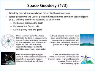
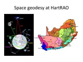
SLR VLBI GPS DORIS Satellite Laser Ranging Doppler Orbitography and Radio Positioning Integrated by Satellite Very Long Baseline Interferometry Global Positioning System Background • Space geodetic systems provide the measurements that are needed to define and maintain an International Terrestrial Reference Field (ITRF) • The ITRF is realized through a combination of observations from globally distributed SLR, VLBI, GNSS, and DORIS systems • NASA contributes SLR, VLBI and GNSS systems to the global network, and has since the Crustal Dynamics Project in the 1980’s • But: the NASA systems are mostly “legacy” systems
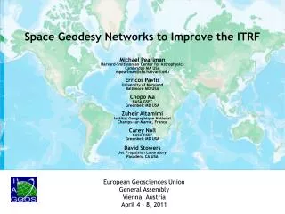
ITRF Requirements • Requirements for the ITRF have increased dramatically since the 1980’s • Most stringent requirement comes from sea level studies: • “accuracy of 1 mm, and stability at 0.1 mm/yr” • This is a factor 10-20 beyond current capability • Simulations show the required ITRF is best realized from a combination solution using data from a global network of ~30 integrated stations having all available techniques with next generation measurement capability • The current network cannot meet this requirement, even if it could be maintained over time (which it cannot) • The core NASA network is deteriorating and inadequate
Geodetic Precision and Time Scale http://dels.nas.edu/Report/Precise-Geodetic-Infrastructure-National-Requirements/12954
NRC Recommendations • Deploy the next generation of automated high-repetition rate SLR tracking systems at the four current U.S. tracking sites in Hawaii, California, Texas, and Maryland; • Install the next-generation VLBI systems at the four U.S. VLBI sites in Maryland, Alaska, Hawaii and Texas; • Deploy additional stations to complement and increase the density of the international geodetic network, in a cooperative effort with its international partners, with a goal of reaching a global geodetic network of fundamental stations; • Establish and maintain a high precision GNSS/GPS national network constructed to scientific specifications, capable of streaming high rate data in real time; • Make a long-term commitment to maintain the International Terrestrial Reference Frame (ITRF) to ensure its continuity and stability; • Continue to support the activities of the GGOS; • Make a long term commitment to the maintenance of ITRF. http://dels.nas.edu/Report/Precise-Geodetic-Infrastructure-National-Requirements/12954
NASA Response • Build a new global network of integrated next generation SLR, VLBI, and GNSS stations • Network should be there for the coming Decadal Survey missions • NASA proposes to provide 6-10 of these stations if the next generation technology can be demonstrated to function as required • Next Generation SLR and VLBI technology pathways known and under development.
Goals of the Space Geodesy Project • Establish and operate a prototype next generation space geodetic station with integrated next generation SLR, VLBI, GNSS (and DORIS) systems, along with a system that provides for accurate vector ties between them. • Develop a Project Implementation Plan for the construction, deployment and operation of a NASA network of similar next generation stations that will become the core of a larger global network of modern space geodetic stations.
Goddard Geophysical and Astronomical Observatory (GGAO) • Goddard Geophysical and Astronomical Observatory is located 5 km from Goddard Space Flight Center in the middle of the Beltsville Agricultural Research Center. GGAO is one of the few sites in the world to have all four geodetic techniques co-located at a single location. MV-3 VLBI VLBI2010 GGAO GNSS 48” Reference mark GSFC MOBLAS-7 NGSLR DORIS
System Features: 1 to 2 arcsecond pointing/tracking accuracy Track CCR equipped satellites to 20,000 km altitude, 24/7 operation Reduced ocular, chemical, electrical hazards Semi automated tracking features Small, compact, low maintenance, increased reliability Lower operating/replication costs NGSLR Development at GGAO NGSLR is a high repetition rate singe photon detection laser ranging system capable of tracking cube corner equipped satellites in Earth orbit. The concept of NGSLR was developed by J. Degnan (GSFC, retired) in the 1990s. Technical development continues at Goddard. The system has demonstrated tracking of Earth orbit satellites with altitudes from ~ 1000 km to 20000 km. Completion of the NGSLR prototype will occur during the Space Geodesy Proposal. OMC ranging plot of satellite returns Four quadrant satellite returns
VLBI 2010 • Smaller antennas (~12m), fast moving, operating unattended, mechanically reliable, economically replicable – more observations for troposphere and geometry – Patriot antenna • Broad continuous frequency range (~2-12 GHz) using multiple bands – smaller observation error and interference avoidance – QRFH feed • Higher speed recording, increased sensitivity –Mark5C recorder • Transfer data with combination of high speed networks and high rate disk systems
Co-location Vector Monitoring • Automated measurement of inter-instrument vectors is an essential aspect of an integrated space geodesy station • Measurements provide closure between terrestrial reference frames derived from different space geodesy techniques • Tests of technologies and currently available systems underway at GGAO
Schedule • Two year delivery schedule. • Task 1: Network Design Studies • Task 2: Prototype Station Development • Task 3: Implementation Plan • Major Milestones: • Prototype Station Integrated at T+18 months • Station Performance Verification at T+24 months • Implementation Plan at T+24 months
Major Subsystems • Time & Frequency • Telescope • Transceiver Bench • Laser • Laser Hazard Reduction System (LHRS) • Tracking • Receiver • Computer and Software • Weather • Shelter and Dome
NGSLR System Characteristics • Telescope: • 40 cm Telescope Aperture Off-Axis Parabola, • No Central Obscuration • Tracking Mount: • AZ/EL with 1 arcsec RMS gimbal pointing accuracy. • Transceiver Bench: • Common Optics for Transmit and Receive • Passive Transmit/Receive Switch • Risley Prism Point-Ahead of Transmit • Laser: • Subnanosecond pulse, 2 kHz • Asynchronous PRF, software controlled • Divergence control by software • Receiver: • High QE, GaAsPMicrochannel Plate Photomultiplier • Constant Fraction Discriminators • GPS-synchronized Rubidium Oscillator /Time and Frequency Receiver • Picosecond Precision Event Timer • Weather: • Day/Night All-Sky Cloud Sensor (thermal) • Wind Monitor • Surface Pressure, Temperature, and Humidity Monitors • Visibility/Precipitation Sensor
VLBI2010 Accomplishments to Date • Mounted cryogenic broadband feeds on antennas at Westford, MA and GGAO • Record 512 MHz from 4 bands between 2 GHz and 14 GHz • Dual linear polarizations • Down converted each band using flexible Up-Down Converter (UDC) • Separated each band into 32 MHz channels using Digital Backend (DBE) • Recorded 2 Gbps on each of 4 Mk5B+ recorders • Installed fast 12-m Patriot antenna to significantly increase observations • Measured antenna aperture efficiency 60%, SEFD 2600 Janskys • VLBI2010 data expected to be phase delay with much lower uncertainty than current group delay observable • Entire VLBI2010 system is newly designed. Some currently deployed equipment dates from the 1970s 18
Typical GNSS Monument • http://facility.unavco.org/kb/questions/104/UNAVCO+Resources%3A+GNSS+Station+Monumentation *depends upon the material the monument is set within**cost for monumentation only; does not include antenna mount or anything above (permits, site-prep, SCIGN mount, radome, etc.)
GNSS SGP Station Integration • Cutaway of braced monument showing proposed Optical target placement (red), SCIGN radomeand mount • Infrastructure requires continuous power and internet with fixed IP • Receivers are to be multi-constellation capable e.g., Javad Delta or equivalent. • Antenna - dome combinations are to be calibrated and IGS recognized
PI (Frey, 698) Deputy PI (Webb, JPL) Project Manager/ Systems Engineer Merkowitz (698) SGP Organization VLBI2010 Lead Ma (698) NGSLR Lead McGarry (694) GNSS Lead Stowers (JPL) Vector Tie Lead Long (224) Data Center Lead Noll (690.1) Site Select. Lead Pearlman (SAO) Simulations Lead Pavlis (UMBC)