Download

1 / 40
530 likes | 1.16k Vues
A Train of Closed Feed Water Heaters . P M V Subbarao Professor Mechanical Engineering Department I I T Delhi. A Trade off between Irreversibility and Reliability !!!. Diagram of Large Power Plant Turbine . Typical Modern Power Plant Turbine . HP Turbine Rotor. LP Turbine Rotor.

E N D
A Train of Closed Feed Water Heaters P M V Subbarao Professor Mechanical Engineering Department I I T Delhi A Trade off between Irreversibility and Reliability !!!
LP LP Block Diagram of A Large Steam Turbine Main Steam Reheat Steam HP IP IP Steam for Reheating OFWH 4 CFWH 3 CFWH 2 CFWH 6 CFWH 5 CFWH 1 Condenser
THERMODYNAMIC CYCLE OPTIMIZATION Effect of Higher Steam Conditions on Unit Performance • As the first step in the optimization of cycle steam conditions, the potential cycle efficiency gain from elevating steam pressures and temperatures needs to be considered. • Starting with the traditional 165 bar/5380C single-reheat cycle, dramatic improvements in power plant performance can be achieved by raising inlet steam conditions to levels up to 310 bar and temperatures to levels in excess of 600 C. • It has become industry practice to refer to such steam conditions, and in fact any supercritical conditions where the reheat steam temperatures exceed 566 C, as “ultrasupercritical”.
Heater Selection and Final Feedwater Temperature In order to maximize the heat rate gain possible with ultrasupercritical steam conditions, the feedwater heater arrangement also needs to be optimized. • In general, the selection of higher steam conditions will result in additional feedwater heaters and a economically optimal higher final feedwater temperature. • In many cases the selection of a heater above the reheat point (HARP) will also be warranted. • The use of a separate desuperheater ahead of the top heater for units with a HARP can result in additional gains in unit performance. • Other cycle parameters such as reheater pressure drop, heater terminal temperature differences, line pressure drops and drain cooler temperature differences have a lesser impact on turbine design, but should also be optimized as part of the overall power plant cost/performance trade-off activity.
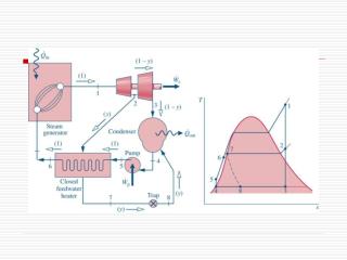
Analysis of Regeneration through CFWH Define y as fraction of mass extraction:
Bleed Steam Feed Water in C Feed Water out DC DS Bled steam Condensate T C DC L C=Condenser DC=Drain cooler Feedwater heater with Drain cooler and Desuperheater DS=Desuperheater TTD -TTD=Terminal temperature difference DS
Desuperheating Zone - The integral desuperheating zone envelopes the final or hotest feed water pass and is thermally engineered to assure dry wall tube conditions with a minimum zone pressure loss. • Dry wall conditions in this zone provide maximum heat recovery per square foot of transfer surface by taking full advantage of the available temperature differential between the superheated steam and the feedwater. • Dry wall conditions also prevent flashing, which is detrimental to proper desuperheating zone operation. • All desuperheating zones are analyzed to make sure they are free of destructive vibration.
HP Turbine Tbi, pbi, Tbsi Condensing Shell Drain Cooler Desuperheater Tfi Tfi+1 TRAP HP Closed Feed Water Heater
Tbi, pbi, Tbsi Condensing Shell Drain Cooler Desuperheater Tfi Tfi+1 TRAP Tf Tube length
LP Closed Feed Water Heater LP Turbine Tbi, pbi, Tbsi Condensing Shell Drain Cooler Tfi Tfi+1 TRAP
Drain Subcooling Zone - When the heater drains temperature is required to be lower than the heater saturation temperature, a drain subcooling zone is employed. • The drain subcooling zone may be either integral or external, and as a general rule, it is integral. • The integral drain subcooling zone perates as a heat exchanger within a heat exchanger, since it is isolated from the condensing zone by the drain subcooling zone end plate, shrouding, and sealing plate. • This zone is designed with generous free area for condensate entrance through the drains inlet to minimize friction losses which would be detrimental to proper operation. • The condensate is subcooled in this zone, flowing up and over horizontally cut baffles.
Tbi, pbi, Tbsi Drain Cooler Tfout Condensing Shell Tfin TRAP Tf Tube length
Work done by Bleed Steam Work done by bleed (extracted) steam:
Closed Feed Water Heaters (Throttled Condensate) 1 2 3 4 5 12 9 6 10 7 8 11
Analysis of Regeneration through Two CFWH 1 T 10 2 12 9 11 3 7 6 4 8 5 s Define y as fraction of mass extraction:
1 T 10 2 12 9 11 3 7 6 4 8 5 s
6 5 4 3 2 1 GSC DC 3 2 5 1 4 6 GSC DC
The Mechanical Deaerator • The removal of dissolved gases from boiler feedwater is an essential process in a steam system. • Carbon dioxide will dissolve in water, resulting in low pH levels and the production of corrosive carbonic acid. • Low pH levels in feedwater causes severe acid attack throughout the boiler system. • While dissolved gases and low pH levels in the feedwater can be controlled or removed by the addition of chemicals. • It is more economical and thermally efficient to remove these gases mechanically. • This mechanical process is known as deaeration and will increase the life of a steam system dramatically.
Deaeration is based on two scientific principles. • The first principle can be described by Henry's Law. • Henry's Law asserts that gas solubility in a solution decreases as the gas partial pressure above the solution decreases. • The second scientific principle that governs deaeration is the relationship between gas solubility and temperature. • Easily explained, gas solubility in a solution decreases as the temperature of the solution rises and approaches saturation temperature. • A deaerator utilizes both of these natural processes to remove dissolved oxygen, carbon dioxide, and other non-condensable gases from boiler feedwater. • The feedwater is sprayed in thin films into a steam atmosphere allowing it to become quickly heated to saturation. • Spraying feedwater in thin films increases the surface area of the liquid in contact with the steam, which, in turn, provides more rapid oxygen removal and lower gas concentrations.
This process reduces the solubility of all dissolved gases and removes it from the feedwater. • The liberated gases are then vented from the deaerator. • Correct deaerator operation requires a vessel pressure of about 20 – 30 kPa above atmospheric, and • a water temperature measured at the storage section of 50C above the boiling point of water at the altitude of the installation. • There should be an 45 – 60 cm steam plume from the deaerator vent, this contains the unwanted oxygen and carbon dioxide. • The following parameters should be continuously monitored to ensure the correct operation of the deaerator. • Deaerator operating pressure. • Water temperature in the storage section.