TUTORIAL ON HARMONICS
TUTORIAL ON HARMONICS. Theory and Computation Techniques C.J. Hatziadoniu: hatz@siu.edu. AC Drive Harmonics. Harmonic Sources: Power converter switching action Motor own generated harmonics (spatial distribution of windings, stator saturation) Transformer/inductor iron core saturation

TUTORIAL ON HARMONICS
E N D
Presentation Transcript
TUTORIAL ON HARMONICS Theory and Computation Techniques C.J. Hatziadoniu: hatz@siu.edu
AC Drive Harmonics Harmonic Sources: • Power converter switching action • Motor own generated harmonics (spatial distribution of windings, stator saturation) • Transformer/inductor iron core saturation • Harmonics flowing between generator and motor sides
Potential Problems due to Harmonics • Power losses and heating: reduced efficiency, equipment de-rating • Over-voltage and voltage spiking, due to resonance: insulation stressing, limiting the forward and reverse blocking voltage of power semiconductor devices, heating, de-rating • EMI: noise, control inaccuracy or instability • Torque pulsation: mechanical fatigue, start-up limitation
Power Loss and Heating • Losses into the resistive and magnetic components • Resistive losses: skin effect • Magnetic losses: Eddy currents and hysterisis losses increase with frequency
Over-Voltage, Over-Current (due to resonance) Capacitor loss due to harmonics (insulation loss)
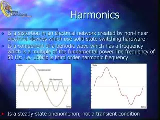
What Are Harmonics? • Technical Description A high frequency sinusoidal current or voltage produced by certain non-linear and switching processes in the system during normal periodic operation (steady state); • The harmonic frequency is an integer multiple of the system operating frequency (fundamental). • The non-sinusoidal part in a periodic voltage or current is the harmonic ripple or harmonic distortion—comprised of harmonic frequencies. • Mathematical Definition • Sine and cosine functions of time with frequencies that are integer multiples of a fundamental frequency • Harmonic sine and cosine functions sum up to a periodic (non-sinusoidal) function • Terms of the Fourier series expansion of a periodic function;
Harmonic Analysis • What is it? • Principles, properties and methods for expressing periodic functions as sum of (harmonic) sine and cosine terms: • Fourier Series • Fourier Transform • Discrete Fourier Transform • Where is it used? • Obtain the response of a system to arbitrary periodic inputs; quantify/assess harmonic effects at each frequency • Framework for describing the quality of the system input and output signals (spectrum)
Superposition • A LTI system responds linearly to its inputs • ui1uo1, ui2uo2 • aui1+bui2auo1+buo2 • For sinusoidal inputs:
Application preview: DC Drive Find the armature current io(t) below
Procedure to obtain response Step 1: Obtain the harmonic composition of the input (Fourier Analysis) Step 2: Obtain the system output at each input frequency (equivalent circuit, T.F. frequency response) Step 3: Sum the outputs from Step 2.
Fundamental Theory Outline • Harmonic Fundamental Theory—Part a: • Periodic Signals—sinusoidal function approximation • Fourier Series—definition, computation • Forms of the Fourier Series • Signal Spectrum • Applications of the FS in LTI • Wave Form Quality of Periodic Signals
Measures Describing the Magnitude of a Signal • Amplitude and Peak Value • Average Value or dc Offset • Root Mean Square Value (RMS) or Power
Amplitude and Peak Value • Peak of a Symmetric Oscillation
Non-Symmetric Signals • Peak-to-peak variation
Average Value • Signal=(constant part) + (oscillating terms)
AC Signals • Zero Average Value
Root Mean Square Value (RMS) For periodic signals, time window equals one period
Remarks on RMS • RMS is a measure of the overall magnitude of the signal (also referred to as norm or power of the signal). • The rms of current and voltage is directly related to power. • Electric equipment rating and size is given in voltage and current rms values.
Effect of DC Offset New RMS= SQRT [ (RMS of Unshifted)2+(DC offset)2]
RMS and Amplitude • Amplitude: Local effects in time; Device insulation, voltage withstand break down, hot spots • RMS: Sustained effects in time; Heat dissipation, power output
Harmonic Analysis: Problem Statement • Approximate the square pulse function by a sinusoidal function in the interval [–T/2 , T/2]
General Problem • Find a cosine function of period T that best fits a given function f(t) in the interval [0,T] • Assumptions: f(t) is periodic of period T
Approximation Error • Error: Objective: Minimize the error e(t) Method: Find value of A that gives the Least Mean Square Error
Procedure Define the average square error as : E is a quadratic function of A. The optimum choice of A is the one minimizing E.
Optimum Value of A Find dE/dA: Set dE/dA equal to zero
A geometrical interpretation Norm of a function, error, etc is defined as:
Approximation with many harmonic terms Average Square Error :
Harmonic Basis The terms From an orthogonal basis Orthogonality property:
Optimum coefficients • The property of orthogonality eliminates the cross harmonic product terms from the Sq. error • For each n, set
Optimum coefficients • Obtain the optimum expansion coefficients:
Waveform Recovery n=1-3 n=1-5 n=1-7 n=1-9 n=1