Download
1 / 5
50 likes | 200 Vues
150Hz. 356mV rms. 338mV rms. 50Hz. 214mV rms. 600Hz. 106mV rms. |Z -1 | [dB]. 250Ω -1. 2.5mΩ -1. 1.83mHz. Harmonics solenoid at 30kA. EXAMPLE CASE (150Hz): |Y| at 150Hz = 2.5mS |I| at 150Hz = 338mV x 2.5mS = 0.845mA rms = = 1.2mA pk Tf = 0.5T / 31kA = 16.1 x 10 -6 T/A

E N D
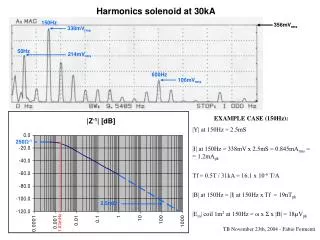
150Hz 356mVrms 338mVrms 50Hz 214mVrms 600Hz 106mVrms |Z-1| [dB] 250Ω-1 2.5mΩ-1 1.83mHz Harmonics solenoid at 30kA EXAMPLE CASE (150Hz): |Y| at 150Hz = 2.5mS |I| at 150Hz = 338mV x 2.5mS = 0.845mArms = = 1.2mApk Tf = 0.5T / 31kA = 16.1 x 10⁻⁶ T/A |B| at 150Hz = |I| at 150Hz x Tf = 19nTpk |Ein| coil 1m2 at 150Hz = ω x Σ x |B| = 18µVpk TB November 23th, 2004 - Fabio Formenti
40mV IEC 478-3/C 2mV 3.16mV IEC 478-3/C Solenoid Vdc + and – at 12kA 1mV At the power converter outputs; same spectrum for both polarities IEC 478-3/C specs for conducted noise very stringent (not for such large devices, but typically 25A-400V) High noise due to environment radiated noise More filtering capacitors will be added Poorly shielded and earthed converter body To be checked and improved TB November 23th, 2004 - Fabio Formenti
40mV IEC 478-3/C 2mV 3.16mV IEC 478-3/C 1mV Solenoid Vrb24 and Vrb26 at 12kA At the solenoid magnet inputs; same spectrum for both polarities Noise practically acceptable; large massive magnet body acts as good ground reference To be rechecked after added filtering capacitors at power converter TB November 23th, 2004 - Fabio Formenti
TPC FE electronics inside solenoid Sum of chs 0,1,2,3 undersampling:100 MAGNET ON • Quadratic sum of noise contributions is: • 1.05 ADC counts [r.m.s.] • Mean value of sum of 4 chs baselines is: • 194 ADC counts Sum of chs 0,1,2,3 undersampling:100 MAGNET OFF • Same mean value • Practically same sigma Measurements by: R.Campagnolo, B. Mota, C. Gonzales TB November 23th, 2004 - Fabio Formenti
Conclusions • Solenoid power has been characterized in harmonics, low and high spectrum EMC • Dipole also characterized similarly (all results will be on E.Coord. page) • Harmonics will not be a problem: • low induced magnetic field perturbations • frequencies lower than interest range (for IN P/A) • local power filters enough to cancel any residuals • Conducted noise EMC is practically already acceptable: • improve shielding and filtering of power converter body • Test of TPC FE electronics inside solenoid did not show any measurable noise • Due thanks for the help provided: • C. De Almeida Martins AB-PO measurements on harmonics and EMC • W. Venturini and C. Giloux AT-MTM consultation on magnetic tests • PH-ED TPC team measurements with FE electronics TB November 23th, 2004 - Fabio Formenti