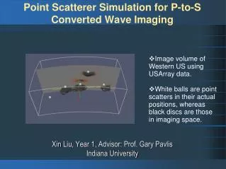
Wave simulation
Matt Wash, Mihai Fota , Panagiotis Armagos. Wave simulation. Introduction. Water simulation created by a 3 man group: Matt Wash, Mihai Fota and Panagiotis Armagos Water must be realistically rendered, the waves must be affected by the depth of the ocean;


Wave simulation
E N D
Presentation Transcript
Matt Wash, MihaiFota, Panagiotis Armagos Wave simulation
Introduction • Water simulation created by a 3 man group: Matt Wash, MihaiFota and PanagiotisArmagos • Water must be realistically rendered, the waves must be affected by the depth of the ocean; • The water surface must reflect the light coming from the sky; • The shore must be curved and the waves must reflect correctly when encountering the shoreline;
Heightmap rtvsD3dWinLite rtvsD3dApp Camera Waves Timer Sky waveTrain Class Diagram • The group took an object oriented development process; • The class diagram for the project:
Implementation • Wave Generation • Height map • Sky Box • Rendering • Interface
Wave Generation The wave simulation was implemented in two main classes - waves responsible for creating, updating and rendering the wave mesh. - waveTrain Encapsulates all parameters and functionality required to execute the simple model of ocean waves.
waves class • Created in setupDX() • Has its own cleanupDX() method. • Constructor takes an initInfostruct that describes mesh size, resolution and depth map file. _pWaves = new waves(wavesInfo, _dirLight, pd3dDevice);
waves class • Creates LPD3DXMESH object. • normalMapVertex • Each calculated initial vertex position is stored in a separate vector<D3DXVECTOR3> member variable. • D3DXComputeTangentFrame() • Initializes 2waveTrain objects passing a heightmap class instance to each.
waves class _pWaveTrain1 = newwaveTrain(0.4f, 0.7f, _depthMap); _pWaveTrain1->applyWind(_windSpeed, _windDirection); _pWaveTrain2 = newwaveTrain(10.5f, 0.4f, 0.0f, 0.3f, _depthMap);
waves class • Executing the simulation - Every frame, in rtvsD3dApp:display(), the update() method is called on the waves class instance. - Iterates over the vertices in the wave mesh, evaluating each one for both waveTrains and interpolating between the newly calculated vertex positions.
waves class // for each vertex for (DWORD v=0; v<_vertices; v++) { // ask the wave trains to evaluate the vertex, returning a new position. D3DXVECTOR3 newPos1 = _pWaveTrain1->evaluateSurfacePoint(v, _initialVertPositions[v], pVertexData->pos.y, phaseShift); D3DXVECTOR3 newPos2 = _pWaveTrain2->evaluateSurfacePoint(v, _initialVertPositions[v], pVertexData->pos.y, phaseShift); // interpolate the resulting positions from each wave train to get the final position. D3DXVECTOR3 finalPos = (_waveTrainLerpVal * newPos1) + ((1.0f - _waveTrainLerpVal) * newPos2); // update the vertex in the buffer. pVertexData->pos.x = finalPos.x; pVertexData->pos.z = finalPos.z; pVertexData->pos.y = finalPos.y; pVertexData++; }
waveTrain class • Has member variables for - wave amplitude (r) - angular velocity - wind shear - wave shape - wave number at infinite depth (Kinf) - wave direction • Kinf = wave shape / r
waveTrain class • Pre-computing wave data - depthMap parameter specifies the relative depth at each vertex in the wave mesh. - As we have Kinf we can pre-compute k for each depth value using:
waveTrain class - Can pre-compute components of equations used to model waves breaking on the shore. - Depth - Three scaling constants - ko, kx,kz - Slope of bottom in direction of wave travel, y (assume this is constant). - All pre-computed data for each vertex is stored in a struct...
waveTrain class structwaveVertexData { float depth; float k; float cosAlpha; float sinAlpha; float Sx; float Sz; };
waveTrain class - precomputeWaveData() method iterates over each value in the heightmap and performs the pre-computation, storing the results in a vector of waveVertexDatastructs: waveVertexData data; // depth data.depth = depthMap(i, j); // wave number data.k = _kInf / (sqrtf(tanhf(_kInf * data.depth))); // wave breaking data (elliptical orbits in shallow water) float alpha = gamma * expf(-ko * data.depth); data.sinAlpha = sinf(alpha); data.cosAlpha = cosf(alpha); data.Sx = 1.0f / (1.0f - expf(-kx * data.depth)); data.Sz = data.Sx * (1.0f - expf(-kz * data.depth)); _precompData.push_back(data);
waveTrain class - Whenever the user changes the amplitude or wind speed parameters for wave train 1 via the UI controls, only the wave number, k, must be recomputed for each vertex. - recomputeWaveNumbers()
waveTrain class • Evaluating each vertex: - waves::executeSimulation() method iterates over vertices i n wave mesh calling evaluateSurfacePoint() on both wave trains...
waveTrain class waveTrain::evaluateSurfacePoint(DWORD ordinal, D3DXVECTOR3 restPos, float deltaY, float phaseShift) { waveVertexDatadata = _precompData[ordinal]; _amp = _waveShape / data.k; float phaseAngle = (data.k* D3DXVec3Dot(&_direction, &restPos)) - (_w * phaseShift) - (_windShear * deltaY); D3DXVECTOR3 newPos; newPos.x= restPos.x + (_direction.x * _amp * data.cosAlpha * data.Sx* sinf(phaseAngle) + data.sinAlpha * data.Sz * cosf(phaseAngle)); newPos.z= restPos.z + (_direction.z * _amp * data.cosAlpha * data.Sx* sinf(phaseAngle) + data.sinAlpha * data.Sz * cosf(phaseAngle)); newPos.y= -_amp * data.cosAlpha * data.Sz * cosf(phaseAngle) + data.sinAlpha* data.Sx * sinf(phaseAngle); // return the result return newPos; }
Height Map • There were a few attempts to make the height map using • .x files created in Blender • .tgs files • .raw file • Raw file were chosen because • Easier to read bytes • Contain more info than any other format • The data are stored in a look up table and then they are • scaled and offset at a predetermined value • Filtered with neighboring pixels to smoothen the result
The Code • Heightmap.cpp • Byte reading: • inFile.read((char*)&rawbytes[0], (streamsize)rawbytes.size()); • Scaling and offset. Data is stored in a lookup table mHeightmap: • mHeightMap(i, j) = (float)rawbytes[k] * heightScale + heightOffset; • Filtering the height data between 8 neighboring pixels: • avg += mHeightMap(m,n); • num += 1.0f; • We return avg / num • rtvsD3dApp.cpp • Call the function • mHeightmap.loadRAW(128, 128, "5.raw", 2.5f, 0.0f); • Modify the grid • pVertexData[index].x = pMeshRestPositions[index].x; • pVertexData[index].y = mHeightmap(row,col); • pVertexData[index].z = pMeshRestPositions[index].z;
Skybox • Terragen 2.0 was used to create the skybox • Six cameras were setup up for the six faces of the cube • Photos were put together in DirectX Texture tool • The skybox is created • HR(D3DXCreateSphere(pd3dDevice, skyRadius, 30, 30, &_sphere, 0)); • The sky is always centered about the camera’s position • D3DXVECTOR3 p = cam.getPosition(); • D3DXMatrixTranslation(&W, p.x, p.y, p.z); • HR(_fx->SetMatrix(_hWVP, &(W * cam.getViewMatrix() * matProj))); • Image size of each face 1024x1024 • The cube is set and textured with 2D images
Rendering • Techniques employed were chosen as I believed they would enhance the wave simulation, making it more realistic. • All rendering is achieved through use of vertex and pixel shaders – sky.fx and waves.fx.
Rendering • A pair of normal maps is scrolled slowly over the surface of the wave mesh in the vertex shader. • Average normal is used when looking up reflected surface colour in sunset cubemap in the pixel shader. • Reflected surface colour is blended with “water” material to create a slowly rippling surface.
Rendering • Foam - Use pixel shader to blend in a foam texture where appropriate. - Use the saturated dot product of the pixel normal and a vector pointing directly upwards as an indicator of where and how much foam texture to blend.
Rendering • Pixel color is sampled from the foam texture map: float3 foamColor = tex2D(FoamMap, tex0); • Amount of foam is then calculated as described earlier and multiplied by a user-specified bias to achieve the desired effect: float3 vecUp = {0.0f, 1.0f, 0.0f}; float foamAmt = (1.0f - saturate(dot(vecUp, normalW))) * gFoamBias; << code omitted for brevity >> • Final material and foam colours are then linearly interpolated according to the foam amount: ambientMtrl = lerp(ambientMtrl, foamAmt, foamColor); diffuseMtrl = lerp(diffuseMtrl, foamAmt, foamColor); • Results in a visible foam effect for steep waves, waves affected by wind shear and those breaking on the shore.
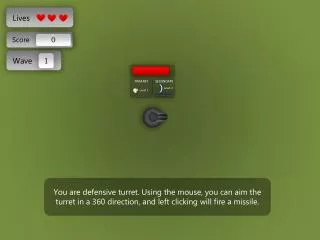
Interface • The interface allows the user to change the shape and movement speed and direction of the waves; • The interface was created using the DXUT architecture from the DX 9 SDK: DXUTSetCallbackMsgProc( msgProc ); DXUTSetCallbackKeyboard( keyboardProc ); DXUTSetWindow(g_hWnd, g_hWnd, g_hWnd, true); DXUTSetDevice(g_pd3dDevice); g_sampleUI.SetCallback( onGUIEvent );
Interface • The interface contains a slider, combo box, and a checkbox; • Tho following code adds the elements to the interface: g_sampleUI.AddSlider( IDC_SLIDER, 200, 450, 200, 24, 10, 30, 20, false ); g_sampleUI.AddCheckBox(IDC_CHECKBOX, L"Environment Map", 170, 450, 350, 24, false, 0, false ); CDXUTComboBox* pCombo; g_sampleUI.AddComboBox( IDC_COMBOBOX, 0, 0, 200, 24, L'O', false, &pCombo); • The “OnGuiEvent” function handled the callback event from the interface elements.
Remaining Issues • Shore mesh integration • D3DXComputeTangentFrame • Window resize
Conclusion • Achieved aims & objectives. • Some areas could have been improved: - Some of Fournier’s equations were simplified. - Wave train concept. - Particle system for spray. - Level of detail algorithm with multiple seamless meshes of varying resolution.