Electromagnetic Wave Theory
Electromagnetic Wave Theory. Lecture 7. Electromagnetic Radiation Fundamentals of electromagnetic waves Effects of environment Propagation of waves Surface waves Ionospheric Propagation. Ionospheric Propagation Ionospheric structure Critical frequency Maximum useable frequency

Electromagnetic Wave Theory
E N D
Presentation Transcript
Electromagnetic Wave Theory Lecture 7
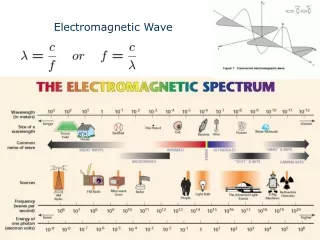
Electromagnetic Radiation • Fundamentals of electromagnetic waves • Effects of environment • Propagation of waves • Surface waves • Ionospheric Propagation
Ionospheric Propagation • Ionospheric structure • Critical frequency • Maximum useable frequency • Optimum working frequency • Lowest useable frequency • Line of sight propagation
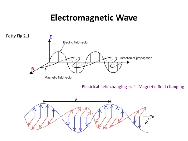
Electromagnetic Radiation • Electricity and electromagnetic waves are related. • The electrical energy generated in a circuit is converted into electromagnetic energy. • An electromagnetic field is made up of an electric and magnetic field. These fields exist within all electric circuits.
The energy within these fields is normally confined within the circuit. • In certain circumstances the energy is radiated or set free from the circuit. • In cases where such a radiation is undesired it is called radio frequency interference.
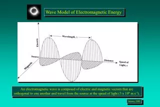
For a radio transmitter the circuit is specially designed to radiate maximum energy. • The electric and magnetic fields are perpendicular to each other and both are also perpendicular to the direction of propagation, as such they are said to be transverse.
Wavefront • If an electromagnetic wave were radiated equally in all directions from a point source, a spherical wavefront would result. Such a source is said to be isotropic. • A wavefront is a plane, which joins all points of equal phase.
Note In this instance the wavefront is spherical, but at large distances from the source the wavefront will become nearly flat.
The power density (in watts per square meter) at a wavefront is inversely proportional to the square of the distance from the source, with respect to the power originally transmitted. In mathematical terms.
where Pt is the power generated at the source. • This is called the inverse square law and it applies to all forms of radiation in free space.
Electric and Magnetic field intensity These are the direct counterparts of voltage and current in circuits. Electric field intensity (E) is measured in volts per meter V/m Magnetic field intensity (H) is measured in amperes per meter A/m. It follows that where z is the characteristic impedance of the medium which is defined as
For free space H/m, permeability of medium F/m, electric permittivity Making the above substitutions
The field strength can therefore be calculated at a distance r from the point source. Just like in electrical circuits, the power for electromagnetic waves can be found by using
Internal Noise making the substitution for and z we obtain
Attenuation and Absorption From the inverse square law it can be established that the power density diminishes rapidly with distance from the source of the electromagnetic waves. The waves are then said to be attenuated as they move away from the source and it is proportional to the square of the distance travelled. The attenuation is measured in decibels is numerically the same for both field intensity and power density.
In free space, absorption of radio waves does not occur, because there is nothing there to absorb them. In the atmosphere some of the energy in the electromagnetic wave is transferred to atoms and molecules in the atmosphere. At frequencies below 10 GHz this absorption is not significant.
Effects of environment When waves are propagated near the earth several factors have to be considered. The waves are subject to reflection by the ground, mountains and buildings. The will also be refracted as they pass through different layers of atmosphere. They can also be diffracted by tall objects.
Reflection of waves Similar to light waves electromagnetic waves are also reflected by a conducting medium. The angle of incidence will be equal to the angle of reflection. The reflection coefficient, is defined as the ratio of the electric intensity of the reflected wave to that of the incident wave. For a perfect reflector it is unity. It is important that the electric vector be perpendicular to the conducting surface. If it is fully parallel to the surface, the electric field is shorted out and all of the energy is dissipated in the form of surface currents.
Refraction This again is similar to the situation in light waves. The angle of incidence equals the angle of refraction, Snell’s law. where is the refractive index of the incident medium, is the refractive index of the refractive medium, is the angle of incidence, is the angle of refraction
Diffraction This is the phenomenon whereby waves travelling in straight paths bend around an obstacle. It is known as Huygens’ principle. This states that each point on a spherical wavefront maybe considered as a source of a secondary spherical wavefront. This concept explains why it is possible to obtain reception behind a mountain or tall building.
Propagation of Waves • The basic modes by which radio waves are transmitted to a receiving antenna are: • Ground (Surface) Waves • Space Waves • Sky Waves • Satellite Communication
Ground Waves These travel along the surface of the earth (more or less following the contour of the earth) and must be vertically polarized to prevent short-circuiting.
They can travel considerable distances, well over the visual horizon. As the wave propagates over the earth, it tilts over more and more. (A current is induced in the earth’s surface by the electromagnetic wave, the result is the wavefront near the surface slows down). This causes the wave to short circuit completely at some distance (in wavelengths) from its source.
This shows that the maximum range of such a transmitter depends on its frequency as well as its power. Increasing the frequency of transmission increases the loss. They are therefore not effective above 2 MHz. It is much better over water than dry ground. They are a reliable communication link. Reception is not affected by daily or seasonal changes. Used effectively to communicate with submarines at extremely low frequencies 30 – 300 Hz.
Field strength at a distance • Radiation from an antenna by means of ground wave taking into consideration the gain of the transmitting antenna at a distance may be found using • If we place a receiving antenna at this point then the signal received in volts will be
where is the characteristic impedance effective height of the transmitting antenna effective height of the receiving antenna I antenna current d distance from the transmitting antenna wavelength
when propagation is over a good conductor such as seawater, at low frequencies, surface absorption is small, the attenuation is equally small. • The angle of tilt is thus the main factor in the long distance propagation of such a wave. • The degree of tilt depends on the distance from the antenna in wavelengths. Low frequency signals have large wavelengths
Example Problems At 20 km in free space from a point source, the power density is 200 . What is the power density at 25 km away from this source?
Calculate the power density at a) 500 m from a 500 W source and b) 36 000 km from a 3 kW source. Assume the source to be isotropic
A deep space high gain antenna and receiver system have a noise figure such that a minimum received power of W is required for satisfactory communication. What must be the transmitting power from a Jupiter probe, situated 800 million km from earth? Assume that the transmitting antenna is isotropic and the equivalent area of the receiving antenna has an area of 8400 m2.
A 150 m antenna transmitting at 1.2 MHz (ground wave), has an antenna current of 8 A. What voltage is received by the receiving antenna 40 km away with a height of 2 m?