Reading Plans and Elevations Module 27104-06
Reading Plans and Elevations Module 27104-06. Transparency 1. Objectives. Upon completion of this module, you will be able to do the following: 1. Describe the types of drawings usually included in a set of plans and list the information found on each type.

Reading Plans and Elevations Module 27104-06
E N D
Presentation Transcript
Reading Plans and Elevations Module 27104-06
Transparency 1 Objectives Upon completion of this module, you will be able to do the following: 1. Describe the types of drawings usually included in a set of plans and list the information found on each type. 2. Identify the different types of lines used on construction drawings. 3. Identify selected architectural symbols commonly used to represent materials on plans. 4. Identify selected electrical, mechanical, and plumbing symbols commonly used on plans. 5. Identify abbreviations commonly used on plans. 6. Read and interpret plans, elevations, schedules, sections, and details contained in basic construction drawings. 7. State the purpose of written specifications. 8. Identify and describe the parts of a specification. 9. Demonstrate or describe how to perform a quantity takeoff for materials.
Transparency 2 Performance Tasks Under supervision of the instructor, you should be able to: 1. Interpret selected symbols and abbreviations used on drawings. 2. Read and interpret site/plot plans. 3. Read and interpret foundation, floor, and other plan view drawings. 4. Read and interpret elevation view drawings. 5. Read and interpret section and detail drawings. 6. Read and interpret schedules. 7. Read and interpret written specifications. 8. Perform a quantity takeoff for materials.
Transparency 3 Figure 1 – Typical Format of a Working Drawing Set
Transparency 4 Figure 2 –Title and Revision Blocks
Transparency 5 Figure 3 –Typical Site Plan
Transparency 6 Figure 4 –Typical Site Plan Showing Topographical Features
Transparency 7 Figure 5 – Foundation Plan (NTS)
Transparency 8 Figure 6 –Slab-on-Grade Foundation Plans (NTS)
Transparency 9 Figure 7 – Basic Floor Plan (NTS)
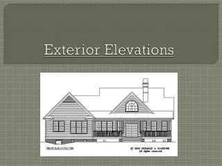
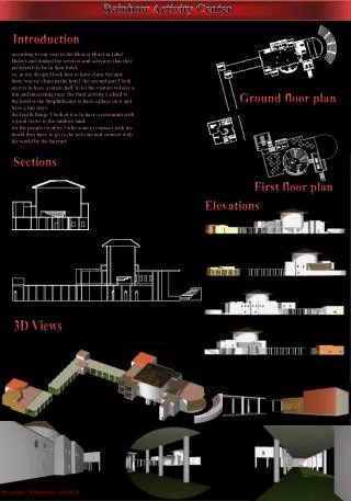
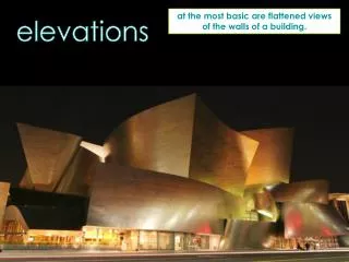
Transparency 10 Figure 8 – Elevation Drawing (NTS)
Transparency 11 Figure 9A –Section Drawing (NTS, 1 of 3)
Transparency 12 Figure 9B – Section Drawing (NTS, 2 of 3)
Transparency 13 Figure 9C –Section Drawing (NTS, 3 of 3)
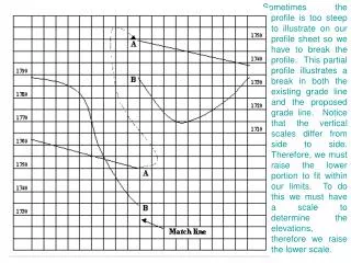
Transparency 14 Figure 10 – Detail Views
Transparency 15 Figure 11 – Examples of Door, Window, and Header Schedules
Transparency 16 Figure 12 – Example of a Finish Schedule
Transparency 17 Figure 13 – Example of an Electrical Plumbing Plan (NTS)
Transparency 18 Figure 14 – Drawing Lines
Transparency 19 Figure 15 – Methods of Labeling Section Reference Lines
Transparency 20 Figure 16 – Typical Material Symbols
Transparency 21 Figure 17 – Window and Door Symbols
Transparency 22 Figure 18 – Common Electrical Symbols
Transparency 23 Figure 19 – Electrical Symbols Showing Control of an Outlet
Transparency 24 Figure 20 – Common Plumbing Symbols
Transparency 25 Figure 21 – Common HVAC Symbols
Transparency 26 Figure 22 – Common Site/Plot Plan Symbols
Transparency 27 Figure 23 – Structural Member Symbols
Transparency 28 Figure 24 – Basic Weld Symbols
Transparency 29 Figure 25 – Elements of a Welding Symbol
Transparency 30 Figure 26 – Common Methods of Indicating Dimensions on Drawings
Transparency 31 Figure 28 – 2004 MasterFormatTM
Transparency 32 Figure 29 – Examples of Project Organizations
Transparency 33 Figure 30 – Typical Residential Construction Schedule
Transparency 34 Figure 31 – Typical Commercial Construction Schedule