Download
1 / 43
460 likes | 803 Vues
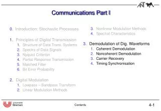
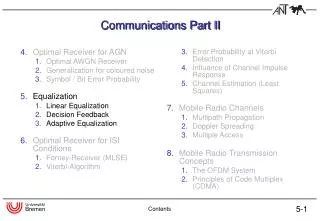
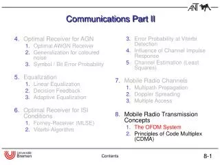
4. Optimal Receiver for AGN Optimal AWGN Receiver Generalization for coloured noise Symbol / Bit Error Probability 5. Equalization Linear Equalization Decision Feedback Adaptive Equalization Optimal Receiver for ISI Conditions Forney-Receiver (MLSE) Viterbi-Algorithm.

E N D
4.Optimal Receiver for AGN Optimal AWGN Receiver Generalization for coloured noise Symbol / Bit Error Probability 5.Equalization Linear Equalization Decision Feedback Adaptive Equalization Optimal Receiver for ISI Conditions Forney-Receiver (MLSE) Viterbi-Algorithm 3. Error Probability at Viterbi Detection 4. Influence of Channel Impulse Response 5. Channel Estimation (Least Squares) Mobile Radio Channels Multipath Propagation Doppler Spreading Multiple Access Mobile Radio Transmission Concepts The OFDM System Principles of Code Multiplex (CDMA) Communications Part II Contents
Introduction: The Multi Carrier Philosophy • single carrier (SC) • equalization problems • multi carrier (MC) • non-selective subchannels Introduction
History of Multi Carrier Technique Introduction
Single Carrier Transmission System (SC) Introduction
Influence of Multipath Propagation on SC Transmission Limits for the raise of transmission rate: Increasing the bandwidth leads to a reduced symbol duration. In case of multipath channels the influence of Inter Symbol Interference (ISI) is amplified. The equalization effort increases dramatically! Introduction
Multi Carrier Transmission (MC) Introduction
Channel influence on MC transmission Advantages of MC over SC: Spreading of data over multiple subcarriers reduces the data rate on each sub channel. This leads to an increased symbol duration which reduces the influence of ISI. The necessary equalization effort can be reduced dramatically! Introduction
Influence of the Channel in Frequency Domain Advantage of multi carrier over single carrier transmission: Increasing the number of subcarriers by reducing the frequency spacing leads to a lower bandwidth of the corresponding subchannels. With a sufficient number of sub-carriers each subchannel can be considered as non frequency selective. In this case the equalization only consists of a multiplicative correction on each subcarrier. The equalization effort can be reduced dramatically! Introduction
Inter Carrier Interference (ICI) Problem of MC: If the frequency bands of different subcarriers overlap, Inter Carrier Interference (ICI) appears. Solution: A special design of transmit and receive filter leads to orthogonality of the subcarriers. Introduction
OFDM transmission system (time continuous) OFDM Basics
Orthogonal Subcarriers OFDM Basics
Mathematical Description of an OFDM System 1/2 • time continuousrepresentation of anOFDM transmitter: • time discreterepresentation ofan OFDM transmitter: OFDM Basics
Mathematical Description of an OFDM System 2/2 • time discreterepresentation ofan OFDM receiver: • Complete System: OFDM Basics
Symbol Rate Model of an OFDM System OFDM Basics
Inter-Symbol- (ISI) and Inter-Carrier-Interference (ICI) OFDM Basics
The OFDM Cyclic Prefix / Guard Interval • The OFDM cyclic prefix serves for the suppression of ISI and ICI ! Why cyclic? * OFDM Basics
OFDM Transmitter(HIPERLAN/2 / IEEE802.11a) • channel coding (convolutional codes with Viterbi decoding) • IDFT: discrete realized filter bank (very efficient FFT) • cyclic prefix / guard interval (GI) prevents intersymbol interference (ISI) OFDM Basics
OFDM Receiver (HIPERLAN/2 / IEEE802.11a) • Synchronization • FFT window position (time domain) • sample and modulation frequency correction • Pre equalizer (PE) for impulse compression • OFDM: Orthogonal Frequency Division Multiplexing • separate multiplicative channel correction on each subcarrier • equalizer coefficient design: en = 1 / Cn circular convolution OFDM Basics
Channel Estimation (CE): Training Symbols • burst structure of HIPERLAN/2 and IEEE802.11a • short symbols for AGCand raw synchronization • training sequence (TS): 2 identical symbols per subcarrier (52) • data OFDM symbols with 48 user data and 4 pilot symbolseach • pilot symbols for fine synchronization (insufficient for channel estimation) Channel Estimation
Nonblind (reference-based) Channel Estimation • Averaging over only two identical training symbols • 2 dB loss in SNR compared to „estimator“ with ideal channel knowledge • Perform additional noise reduction (NR) to increase estimation quality Channel Estimation
Noise Reduction Algorithm (NR) • Background • a-priori knowledge: limited channel impulse response in time domain a channel impulse response fits into guard interval • lowpass filtering in frequency domain • NR algorithm (required operations) • transform the estimated channel transfer function into time domain (IDFT) • truncatethe estimated impulse response (rectangular window) • re-transform into frequency domain (DFT) Channel Estimation
Noise Reduction Algorithm – Example • estimated and real channel transfer functions (frequency domain) • ... in time domain Channel Estimation
Noise Reduction Algorithm – Example • smoothed and real transfer functions (in frequency domain) • time limited (windowed) impulse response Channel Estimation
Noise Reduction Algorithm – Simulation Results • simulation of a HIPERLAN/2 system (27 Mbit/s) • time invariant • Rayleigh distributed • multipath channel • (only CE) • Eb/N0 loss: about 1.8 dB • (CE+NR) • Eb/N0 loss: about 0.5 dB • (ideal) • perfectly known channel Channel Estimation
Channel Tracking – Motivation • PHY burst length < 2 ms (IEEE802.11a: < 5 ms) • Jakes distributed Doppler shift • object speed: 3 m/s (figure: 10 m/s) • time variant channel transfer function a channel tracking is required Channel Tracking
Block Diagram: “Turbo Channel Estimation“ Channel Tracking
Example without Channel Tracking • time variant channel (100 ns, 30 m/s) • HIPERLAN/2 (12 Mbit/s) • burst length: 180 OFDM symbols (720 ms) • CE+NR (no tracking) Channel Tracking
Example with Channel Tracking • time variant channel (100 ns, 30 m/s) • HIPERLAN/2 (12 Mbit/s) • burst length: 180 OFDM symbols (720 ms) • CE+NR+Tracking Channel Tracking
Simulation Results • time variant multipath channel (Jakes distributed Doppler shift) • channel noise • HIPERLAN/2 (27 Mbit/s) • burst length 320 ms • CE+NR Channel Tracking
Parameters of an OFDM System OFDM Summary
4.Optimal Receiver for AGN Optimal AWGN Receiver Generalization for coloured noise Symbol / Bit Error Probability 5.Equalization Linear Equalization Decision Feedback Adaptive Equalization Optimal Receiver for ISI Conditions Forney-Receiver (MLSE) Viterbi-Algorithm 3. Error Probability at Viterbi Detection 4. Influence of Channel Impulse Response 5. Channel Estimation (Least Squares) Mobile Radio Channels Multipath Propagation Doppler Spreading Multiple Access Mobile Radio Transmission Concepts The OFDM System Principles of Code Multiplex (CDMA) Communications Part II Contents
Code Time Frequency Code Time Frequency Multiple Access Schemes Code Division Multiple Access (CDMA): Frequency Division Multiple Access (FDMA): Time Division Multiple Access (TDMA): Code Time Frequency
Principles of Code Division Multiple Access:Block Diagram + user 1 user 2 user U
Principles of Code Division Multiple Access:Spreading Data Signal: Chip sequence: Spreaded data signal: TS 1 -1 * TC 1 -1 = 1 -1
1 1 -1 -1 1 1 -1 -1 1 1 -1 -1 TS TS TS TS Principles of Code Division Multiple Access:Despreading TS TS * * = =
How to choose spreading codes? Walsh Hadamard codes: Orthogonality: Example: t
Orthogonal Codes? Problem: Synchronisation (Uplink) At the transmitter Receiver of user 1 1 1 chip sequence of user 1 -1 -1 1 1 chip sequence of user 2 -1 -1 worst case
Orthogonal Codes? Problem: Multipath channel (Up- and Downlink) 1 chip sequence of user 1 Path 1 -1 1 -1 1 Path 2 -1
1 2 3 4 5 6 1 2 3 4 5 6 z-n Pseudo Random Codes Cross correlation function: Ideal Case: Random code (e.g. m-sequence, Gold-code) mother code 1 Gold code mother code 2
CDMA System and mobile radio channel narrow band signal wideband signal time variant mobile radio channel mobile radio channel 2 mobile radio channel 1
Rake Receiver g-th branch of RAKE: Correlation with code: Multiplication with conjugate channel coefficient: