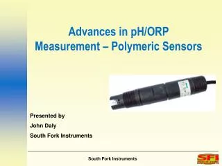
Advances in pH/ORP Measurement – Polymeric Sensors
Advances in pH/ORP Measurement – Polymeric Sensors. Presented by John Daly South Fork Instruments. Introduction.

Advances in pH/ORP Measurement – Polymeric Sensors
E N D
Presentation Transcript
Advances in pH/ORP Measurement – Polymeric Sensors Presented by John Daly South Fork Instruments
Introduction pH probes are generally considered to be consumable items in many plants, with high maintenance overhead and high associated cost. This session introduces Solid State Polymeric sensor technology as an alternative, comparing it to conventional pH sensor technology and describe why challenging and extreme pH applications can be solved using it
Overview pH probes are electochemical devices that react to H2 ions in the liquid being measured - the more H2 ions, the more acidic the liquid. In order to operate correctly, the probe must be in intimate contact with the process fuid, and that is where the problems start…..
pH Measuring Electrode Reference Cell KCl/AgCl liquid KCl/AgCl Gel Ag/AgCl Element Liquid Junction pH Sensitive Glass How pH probes work pH probes consist of two parts – the measurement cell and the reference cell
Li Li Li Li Li Li H+ H+ H+ H+ H+ H+ H+ H+ H+ H+ H+ H+ How the pH Sensitive Glass Works • Lithium Ions in the pH sensitive glass act as current carriers • Positive Charged Free Hydrogen Ions (H+)Develop Positive mV Potential Relative to Internal Buffer • Acidic Solutions • Fewer Hydrogen Ions Relative to Internal Buffer Produce a Negative mV Potential • Alkaline Solutions Internal Fill Solution pH Glass Internal Gel Layer External Gel Layer Process
+ + + + pH Electrode with pH Sensitive Glass Silver/Silver Chloride wire and billet Glass membrane thickness 0.2-0.5 mm Gel layer on both sides of glass Internal Solution: H+ is constant + + - + Glass Matrix + + + - + + + + - Acid solution < 7 Alkaline solution > 7 -
The Reference Electrode and Liquid Junction Silver Wire Electrolyte: Liquid, Gel or Polymer Silver/Silver Chloride Reference Billet Liquid Junction: Ceramic, Wood, or Plastic
Making a pH Measurement pH Measurement
The pH Combination Electrode Circuit E 1 Half-cell voltage Ag/AgCl || KCl (pH electrode), voltage depends on electrolyte concentration E 2 Potential of internal buffer, inside glass membrane E 3 Potental voltage across glass membrane E 4 Variable potential on the outside of the membrane E 5 Flow diffusion potential E 6 Referencediffusion potential E 7 Half-cell voltage Ag/AgCl || KCl (reference electrode), voltage depends on electrolyte concentration Reference Sensor pH Sensor
pH is a Potentiometric Measurement • The Measuring System consists of a pH Measuring Electrode and Reference Electrode • The Potential Difference Between the Two Electrodes is a Function of the pH Value of the MeasuredSolution • The Solution Must Be Conductive and is Part of the Electrical Circuit pH Measuring Electrode Reference Electrode
Reference Cell Problems (1) • In conventional pH probe designs, the reference electrode and reference cell contents are in contact with the process fluid • Under certain conditions, the cell becomes depleted
Reference Cell Problems (2) • Under different conditions, the cell becomes poisoned • Reference cell depletion or poisoning leads to drift and probe failure
Reference Cell Strategies • Double Porous Junction Probes • An additional junction is installed to slow down depletion around the electrode itself and keep poisons out longer • Tortuous Path Electrodes • A long poisoning path is built into the probe to prolong life • Flowing Junction Electrodes • Electrolyte is flowed through the porous junction to prevent ingress of poisons and to maintain electrolyte concentration
The Polymeric Solution • No Porous Junction to allow poisoning and depletion • Polymeric sleeve isolates the reference electrode from the process
Benefits of Polymeric Sensors • Long, long life • Plastic is ionic and takes a long time to deplete • Minimal Zero Drift • Reference is not depleting • Resiliant to fouling • No junction to plug up
Applications • Sour Water • Ultra Pure Water • Waste Water Treatment • Oily Water • Low Ionic Service • Vacuum Service
Summary • Polymeric sensors provide longer life and better stability in “difficult” applications than conventional technology probes. • In “standard” applications, the benefits of polymeric technology are clear – exceptional life and low drift/maintenance requirements South Fork Instruments (925) 461 5059 www.southforkinst.com