Download
1 / 130
1.3k likes | 1.32k Vues
This informative text explores wiring circuits and covers topics such as electrical components, wiring materials and installation methods, and the use of different types of lighting. Students will learn how to differentiate between branch and feeder circuits, plan and wire circuits, and interpret electrical information. The text aligns with ELA and Agriculture, Food, and Natural Resource Common Core Standards.

E N D
Next Generation Science/Common Core Standards Addressed! • CCSS.ELA Literacy.RST.9‐10.1 Cite specific textual evidence to support analysis of science and technical texts, attending to the precise details of explanations or descriptions. • CCSS.ELA Literacy. RST.9‐10.3Follow precisely a complex multistep procedure when carrying out experiments, taking measurements, or performing technical tasks, attending to special cases or exceptions defined in the text. • CCSS.ELA Literacy. RST.9‐10.7 Translate quantitative or technical information expressed in words in a text into visual form (e.g., a table or chart) and translate information expressed visually or mathematically (e.g., in an equation) into words. • RST.11‐12.3 Follow precisely a complex multistep procedure when carrying out experiments, taking measurements, or performing technical tasks; analyze the specific results based on explanations in the text. • HSNQ.A.1 Use units as a way to understand problems and to guide the solution of multi‐step problems; choose and interpret units consistently in formulas; choose and interpret the scale and the origin in graphs.
Agriculture, Food and Natural Resource Standards Addressed! • PST.04.04.02.a. Distinguish electrical circuits and the components of each. • PST.04.04.02.c. Plan and wire electrical circuits (i.e., single pole switch, three-way switch, duplex outlet, etc.).
Interest Approach 1.About where should switches and duplex receptacles located ? 2. How is wire ran from the service entrance panel to the particular place to be wired? 3. How many circuits should be installed in a building?
Bell Work/Student Learning Objectives • 1. Differentiate between branch and feeder circuits and describe the wiring of 120 volt and 240 volt branch and feeder circuits, including color coding and polarity requirements. • 2. Explain wiring materials and installation methods as well as plan and wire circuits to function as specified. • 3. Describe the use of incandescent, fluorescent, and high intensity discharge lighting.
Terms • 3-way switches • 4-way switches • Balanced load • Branch circuits • Cable • Conduit • Duplex convenience outlet (DCO) • Equipment grounding conductor • Feeder circuits • Fluorescent light • Grounded conductor • High intensity discharge (HID) light
Terms (Cont.) • Incandescent light • Individual branch circuit • Metallic conduit • National Electrical Code (NEC) • Nonmetallic conduit • Pole • Special purpose outlet (SPO) • Switch loop • Switch controlled split duplex receptacle • Throw • Ungrounded conductor
All circuits within a building originate in the building’s service entrance panel. • These may be branch circuits or feeder circuits
Branch Circuits • Branch circuits originate in the service entrance panel and serve individual loads or groups of loads. • A circuit breaker or a fuse will serve as overcurrent protection for branch circuit conductors. • Branch circuits are generally 120 volts or 240 volts.
Branch Circuits • 120 volt branch circuits are used to serve general purpose receptacle outlets and lighting fixtures. • No more than 10 duplex convenience outlets (DCO’s) or 10 light fixtures (150 watt maximum) should be wired on a single 20 ampere, 120 volt circuit.
Branch Circuits • Included in a branch circuit are one ungrounded (hot) conductor, one grounded (neutral) conductor, and one equipment grounding conductor.
Branch Circuits • When wiring with cable, the hot conductor is either normally black or red, the neutral conductor is always white, and the equipment grounding conductor is bare.
Branch Circuits • 120 volt circuits should be planned and installed so that the load is balanced at the building’s service entrance panel. • Balanced load means the 120 volt load should be approximately the same on each of the ungrounded service conductors coming into the service entrance panel.
Branch Circuits • In other words, the load should be similar on each side of the circuit breaker box. • An unbalanced 120 volt load may cause tripping of the main disconnect.
240 volt Branch Circuits • Used to serve specific loads, such as stationary motors and appliances, or special purpose outlets.
240 volt Branch Circuits • A special purpose outlet (SPO) is an outlet sized receptacle and is installed to serve a specific plug-and-cord connected appliance.
240 volt Branch Circuits • 240 volt circuits have two ungrounded (hot) conductors and an equipment grounding conductor. • A grounded (neutral) conductor is not required in a regular 240 volt circuit.
240 volt Branch Circuits • The two hot conductors are connected to the double pole circuit breaker at the service entrance panel and to the two brass colored terminal screws at the SPO.
240 volt Branch Circuits • The equipment grounding conductor is connected to the neutral bar of the service entrance panel and to the green grounding screw at the SPO.
240 volt Branch Circuits • When wiring with cable, the white conductor is used as a hot conductor, but must be identified with a black band or black tape at the SPO and at the service entrance panel.
Feeder Circuits • Feeder circuits originate in the service entrance panel and supply power to a sub-panel.
Feeder Circuits • Overcurrent protection devices in the service entrance panel are sized to protect the feeder circuit conductors.
Feeder Circuits • The sub-panel will provide overcurrent protection for the branch circuits originating there. • The circuit connections for a feeder circuit are the same as for a 240 volt branch circuit.
The National Electrical Code (NEC) provides the accepted set of guidelines that should be followed. • When installing electrical equipment and materials, it is of extreme importance to follow approved guidelines and use approved devices and materials.
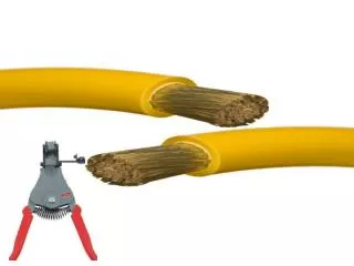
Electric conductors • Electric conductors or wires are made of copper or aluminum. • Aluminum is less expensive and weighs less than copper. • Copper offers less resistance to the flow of electricity, does not have as high a rate of thermal expansion, and has less a problem with oxidation than does aluminum.
Electric conductors • For these reasons, copper wire is preferred over aluminum when wiring most branch circuits. • Aluminum is often used in triplex cable as service conductors into a building.
Electric conductors • There are three basic conductors used in electric wiring.
Electric conductors • A grounded conductor is a conductor intentionally connected to ground. • It is connected to the neutral bar in the service entrance panel (SEP) and is often referred to as a neutral conductor.
Electric conductors • In a 120-volt circuit, the grounded conductor is a normal current carrying conductor.
Electric conductors • According to the NEC, ungrounded conductors AWG #6 or smaller must have white or natural gray colored insulation.
Electric conductors • An equipment grounding conductor bonds conductive materials that enclose electrical conductors or equipment back to the system grounding electrode. • This protects people and property from damage or injury in case of a ground-fault.
Electric conductors • During normal operation, this conductor carries no current. • This conductor is usually uninsulated or bare. • If it is insulated, it must be green or green with one or more yellow stripes.
Electric conductors • An ungrounded conductor originates at the circuit breaker or fuse. • This conductor is usually black or red.
Electric conductors • Choosing the right type and size of conductor is also important.
Electric conductors • Things that must be considered are a. the load in amps required, b. the type of wire being used c. distance of travel the wire must go from the SEP to the load.
Electric conductors • The NEC requires that single wires must be protected from physical damage. When wiring branch circuits, you generally do this by using cable or conduit.
Electric conductors • A cable consists of two or more wires in a protective outer sheath or jacket.
Electric conductors • Each wire must be individually insulated, except for the equipment grounding wire, which may be bare. • The cable may be described based on the cable type, the size of individual conductors, the number of current-carrying conductors within the cable, and whether or not there is an equipment grounding conductor present.
Electric conductors • The 12-2 indicates that the conductors are AWG No. 12 and that there are 2 normal current-carrying conductors in the cable.
Electric conductors • The WG indicates that the cable is “with ground”, meaning that a grounding conductor is contained in the cable.
Conduit • Conduit is a channel or tube through which conductors are run in order to provide the conductors with mechanical protection.
Conduit • The conduit is installed first and the conductors are then “fished” through it to make circuit connections. • Conduit may be metallic or non-metallic.
Conduit • Metallic conduit is made of either galvanized steel or aluminum. • It may also be rigid metal conduit, intermediate metal conduit (IMC), or electrical metallic tubing (EMT). • They are different in their thickness and ability to withstand physical damage.
Conduit • If metallic conduit is properly installed and bonded, it may also serve as the equipment grounding conductor in a branch circuit.
Conduit • Nonmetallic conduit is usually made of polyvinyl chloride (PVC), but can also be made of high density polyethylene, fiberglass, nonmetallic fiber, etc.
Conduit • When properly installed, PVC conduit is dust-tight, watertight, and noncorrosive. • It should be supported at regular intervals, depending on its size and must be supported within 3 feet of each box or other conduit termination point.
Conduit • Avoid running conduit from a cold area to a warm area to avoid moisture condensation in the conduit.
Conduit • The size of conduit required depends on the size of the wires used, type of insulation on the wires, the number of wires to be installed, and whether or not the wires are all the same type and size.
Receptacle outlets • Receptacle outlets provide a convenient means of connecting electrical equipment to the wiring system. • Most outlets are the duplex convenience outlet or the special purpose outlet.
Duplex Convenience Outlet (DCO) • A duplex convenience outlet (DCO) is a general purpose outlet having two receptacles built into one device.