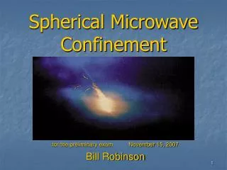
Spherical Microwave Confinement
Spherical Microwave Confinement. An introduction for TUNL October, 2008 Bill Robinson. History. February 1995: Scientific American article on sonoluminescence and fusion got me started looking for exotic energy sources

Spherical Microwave Confinement
E N D
Presentation Transcript
Spherical Microwave Confinement An introduction for TUNL October, 2008 Bill Robinson
History • February 1995: Scientific American article on sonoluminescence and fusion got me started looking for exotic energy sources • 1996-99; investigated various cold fusion ideas, usually shock waves through hydride aerosols; gave up for lots of reasons • July 2000; started investigating idea of helical antennas in a sphere—and thought of coming to NCSU for physics • 2003; started interest in Ball Lightning (BL) • 2004; began grad school in hopes of building a reactor
More History • 2004-2006; went through large number of possible designs with this geometry (including Inertial Electrostatic Confinement [IEC]); ended up with magnetic SMC theory, BL on the side, formal papers • August 2006; started construction in 102-A Research II with Dr. Aspnes as advisor • Spring 2007; obvious that magnets are beyond my capacity in cost, manpower, time; found flaws in theory; concentrating on BL and Spherical Microwave Confinement with no magnets • September 2007; first plasma • October 13 2007; back to SMC as variety of IEC
Inertial Electrostatic Confinement (Ref. 2)
IEC single potential well [3] Fig. 2: Single potential well structure. The minimum normalized potential, Ymin, coincides with the core potential, Ycore = Y(r = 0). The fractional well depth, FWD is defined as FWD = 1-Ymin.
IEC double potential well [3] Fig. 3: Double spheroidal potential well structure. The double well depth (DWD) is Ypeak – Ymin. Here, Ypeak coincides with Ycore. A double well is much more likely in SMC than the single well.
Existing IEC • Large increase of plasma density in potential wells, fosters high rate of reaction there; BUT net reaction rate ~ 1/pressure • IEC with grids cannot (yet) go above Q~10-5 • Big advantages: no B fields, easy high T, simple geometry, some fusion does occur at center and in mantle (zone between grids) • High T makes advanced fuels tempting but elusive so far • IEC operates at too low density for power reactor (need ~1021 m-3 in sizable volume) [5] • IEC is the cheapest way to fusion by a very large factor; reactors are mostly vacuum, thus low mass. • Existing grid reactor can be a practical, portable, simple neutron source (like the STAR reactor), but not efficient enough yet for sub-critical fission or large-scale transmutation. Maximum so far; 2x10¹⁰ neutrons/sec by Hirsch in the ’60s [6] and Nebel in late ’90s • Other attempts for either gridless IEC or to protect grids magnetically from collision (Bussard) have failed (new Bussard-style experiment might do better but far from break-even)
Critical IEC Scaling Problem: 1/n • As density drops, longer mean free path, more acceleration between grids, higher energy, increased <sv>, fewer ion-neutral collisions, tighter focus at center, more head-on collisions. [9] • Thus fusion reactions scale as 1/n instead of n2. IEC reactors operate at very high vacuum << fusion reactor range (1021m-3) • Might not be true of SMC since mfp of runaway electrons are long due to velocity; acceleration from microwaves and grids; less focus anyway
Critical IEC scaling problem; Power ~ 1/a • a = radius of spherical active zone, q = total charge, fa = potential at r = a, ne and ni are average densities in the active zone, P = power from fusion • For grid IEC, q = |ne – ni| ~ ni • fa~ q/a ~ ni a3/a2 = ni a2 • Since fa is within a small range, ni ~ 1/a2 • P ~ ni2 *Volume, so P ~ 1/a • Probably NOT true for SMC since source of ions, electrons, and charge balance is not the same as for grids; q is not ~ ni • Proof of this is the use of ion or electron beams to alter the charge/density relationship in grid IEC to increase P • Result is IEC devices are very small (a few inches) and cannot scale up while SMC probably can
Unavoidable Loss Problems in grid IEC • Collisions with grids; Pgridloss/Pfusion > 3000; particle paths MUST cross grids to be confined [5] • Ion upscatter and energetic tail loss time ~10-3 fusion rate • Ion neutral capture and escape from potential well • Fusion reaction products escape, do not heat plasma (direct energy conversion probably won’t work) [8] • Ion collisions increase angular momentum and throw ions out of dense center region (may not be so bad, double wells can work) • No way to keep plasma non-thermal; collision x-section >> fusion x-section by factor of at least 105 • Bremsstrahlung same or worse as other reactors, makes advanced non-neutronic fuels probablyimpractical (fuel touted as ideal for IEC) • Both ion and electron loss times << fusion time
Some recent IEC experiments Richard Nebel’s Los Alamos Triple-gridded POPS IEC 1010 n/s, $500 k, 25 kW [4] Hitachi IEC, Japan, 7 x 10⁷ n/s
Spherical Microwave Confinement • An RF-powered variation of Electron Accelerated Inertial Electrostatic Confinement (EXL IEC) without internal grids for conventional fusion reactions (D-D, D-T, proton-11B?) • Critical point is to reverse outward-flowing electrons by near-field RF and inward-flowing electron waves before they reach the antennas, instead of requiring transit through grids • If this is correct, the existing hardware could produce large numbers of neutrons. The concept might be developed for power generation in larger and more efficient reactors
SMC Reactor Design • 20 conical, helical antennas for 2.45 GHz RF, 1 wavelength long, 5 turns; aluminum sphere is groundplane • 20 magnetrons (1kW each) fire from cap bank (-6kV to -4kV), ~1/10 sec • Each hemisphere mounted on independent framework on casters • 2 RF shielded windows 2” diameter • Polar pipes (1 ¼”) for access, gas in/out, probes, sparker, fiberoptic • Might accommodate either hemispherical magnets or neutron shields 1 ½ inches off of surface, nearly enclosing the sphere
A Tour of the Lab 2 Video camera Back of rack-mounted control panel and upper capacitor bank From 5 magnetrons to coax Distributing current to the ‘trons
A Tour of the Lab 3; alternatives Old open coils with fresh ceramic Plastic filled coils with ss circular grid, trying shield patterns, effect of ceramic Spraying ceramic inside hemisphere Testing alternate grid with teflon disks at base
Antennas Filling old coils with PVC (not a good idea) to prevent plasma inside helix Casting coils in epoxy Conical helix in plaster mold for Mark II Coating cone with silica composite ceramic Removed epoxy cone
Mark II Antennas Putting on the shields Completed Mk II Copper shield Mounted antennas Riveting triangles to base
Early Video Stills, Ball Lightning (2007) Early shot; 3 torr, sparker loaded with flour and graphite; 30 fps; sparker should be delayed to have maximum during microwave discharge 1) Sparker explodes aerosol 2) Magnetrons start breakdown 3) One of 3 frames, hot plasma 4) Winding down, helix cores last to cool
Evolving video stills Plastic-filled coils; upper shielded, lower shielded and coated with ceramic Open coils, thin wire grid Conical helix in epoxy, ceramic, with bare shield; others no shield, SS grid circles Upper; completed Mark II, middle; bare shield, lower; coil and ceramic
Antennas as e- accelerators • Antennas are insulated with ceramic and do not short out to plasma • Will apply -6 kV (or more) bias to base rings, 4” diameter, 1” from wall. • Microwaves cause breakdown, rapidly saturates to critical density (opaque plasma) • Electron cascade bunches in waves and flows toward center; same process turns back electrons exiting center • Uncoordinated antenna phases now; may be better in phase for inwards-moving spherical waves • Existing rig; ~5 x10⁸ e/cycle at ~25 keV (~0.2 amp) assuming delivering 5 kW to waves from microwaves (efficiency of 0.25) • Bias on base rings limited to no more than electron wave energy ~ virtual cathode potential; 10 kV for D-T reactor, 50 kV for D-D • Ions also bunch in waves, follow e- inwards; qi(t)= <-qe(t-d)> • Inner charge during microwave increase; qtotal = qi - qe = - d <dqe/dt> (qe = # inner electrons) • For each 5 microseconds ion delay, can create 1 kV potential if low electron loss
Current and Future Research (1) • THEORY; see how closely SMC resembles IEC, determine mechanism of near field and interaction with grid at various pressures • Determine energy spectrum of slightly non-Maxwellian plasma • Ion heating; magnetrons are a few MHz out of phase, causes Landau damping [8] • Shock dynamics, if they apply, with antennas in phase or random (current setup is random); compression, heating • Confinement mechanism for electrons in SMC (and maybe Ball Lightning theory?) • Investigate EM knots (alternative Maxwell Equation solutions) • Analyze increased depth of potential well via exit of fusion product ions and ions expelled via POPS • Effect of antenna synchronization vs. independent magnetrons
Current and Future Research (2) • HARDWARE; Diagnostic tools are first priority; computer DAQ, plasma probes, spectrometer, gas analysis, and detectors for x-rays, gammas, alphas, but concentrating on D-D NEUTRONS for now • Upgrade of vacuum system for lower pressures and higher purity of fuel • Hard coating on ceramics to avoid dust • Improvement of microwave circuit (depends on funding); single microwave source, phase and frequency control, lower power and losses, CW, better materials • Monolithic ceramic/Invar antennas (expensive!), better ceramic on inside of sphere compatible with expansion • Given time, might try Ball Lightning experiments
Current and Future Research (3) • GOALS; SMC proven if D-D neutrons are produced at all, is the critical test, must be done in a shielded environment • Thesis ASAP (spring 2009) • Diagnostics of potential well and plasma temperature, density, kinetics, RF fields, reaction volume, energy spectrum • Design of next D-D or D-T reactor as neutron source, en route to--? (Might try p-B11 with decaborane) • Determine how SMC scales in size, plasma density, and RF power; extrapolate to propose pilot power reactor • FUNDING! And a way to continue doing this after graduation—in this area if possible; post-doc?
What I would need at TUNL • Shielded space (~11’ x 6’ minimum) safe for 2.45 MeV neutrons, ~ 1010 / sec (with luck!) • 110 AC power, internet, desk/table space near the reactor, room for electronics rack • 1.5 liter/min tap water for cooling turbo pump • Can borrow fast neutron detector from NCSU for short times but better if can use one from here (and would need guidance on how to use it and MCA…) • Could be ready to ship the gear in November
Appendix A:Periodically Oscillating Plasma Sphere (POPS) Uses RF modulation of grids and emitters to oscillate the potential well in resonance with the orbital frequency of the ions to extend life of virtual cathode (a) Temporal evolution of plasma potential at the center of the virtual cathode with and without rf modulation. (b) Delay in the virtual cathode destruction due to rf modulation as a function of modulation frequency. (Reproduced from Ref. 4.) This is for just a few hundred volts and 10-6 torr
POPS & SMC? • POPS in grid IEC cannot scale to a reactor since • With rvc = virtual cathode radius, fo = potential well depth; note change in radius and compression ratio • Resonant frequency: • At fusion reactor conditions, 10-30 MHz (D-D); milder plasmas down to kHz • Works by throwing a few ions out of potential well. Might use by RF AM modulation of grids or microwaves, or rapidly pulsed injected beams of electrons or ions • Grid IEC needs addition of electrons at center to reduce ion space charge and allow compression, may also in SMC
Appendix B:Magnetic SMC, a possible future addition • Two hemispherical coils, counter-rotating • Uses cylindrical cusp to make electron cyclotron resonance (ECR) on spheroidal B isosurface at 875 gauss • Could help make plasma transparent outside plasmoid • Would heat electrons at ECR surface efficiently and selectively • reactor is constructed to accommodate the coils • Expensive and uses a lot of power if not superconducting • Could funnel reaction products out poles and equator for direct energy conversion Arrows are B field; center circle is plasmoid surface; outer circle is magnet coil
Magnetic SMC Coil windings in amp-turns for test reactor, one hemisphere (other hemisphere is negative of this) Tickmarks are meters; contours are B field magnitudes; dark circle is 875 gauss (ECR); outer circle is magnet; next circle in is pressure wall; dotted circle is inner end of antennas
References • 1) A. Siebenforcher, Rev. Sci. Instrum. 67(3), March 1996 • 2) Tom Ligon, Infinite Energy Issue 30, 2000 • 3) IEC thesis by Ryan Meyer, U. of Missouri-Columbia December 2007 • 4) J. Park, R.A. Nebel, S. Stange, Phys. Plasmas 12, 056315 (2005) • 5) ”A general critique of inertial-electrostatic confinement fusion systems”, Todd Rider, Phys. Plasmas 2 (6), June 1995 • 6) R. L. Hirsch, J. Appl. Physics 38, 4522 (1967) • 7) M. Rosenbluth, F. Hinton, Plasma Phys. Control. Fusion 36 (1994) 1255-1268 • 8) F. Chen, Plasma Physics and Controlled Fusion, 1984 • 9) “Development of a High Fluence Neutron Source for Nondestructive Characterization of Nuclear Waste”, M. Pickrell, LANL Technical Report (1999) • M. Bourham, class notes www.billrobinsonmusic.com/Physics for pictures, papers, latest news