Combinational Logic Design
Combinational Logic Design. Digital Computer Logic Kashif Bashir http://www.taleem.greatnow.com Email: kashif@pafkiet.edu.pk. Module Outline. Combinational Circuits Design Topics Analysis Procedure Design Procedure Decoders Encoders Multiplexers Binary Adders Binary Subtraction


Combinational Logic Design
E N D
Presentation Transcript
Combinational Logic Design Digital Computer Logic Kashif Bashirhttp://www.taleem.greatnow.com Email: kashif@pafkiet.edu.pk
Module Outline • Combinational Circuits • Design Topics • Analysis Procedure • Design Procedure • Decoders • Encoders • Multiplexers • Binary Adders • Binary Subtraction • Binary Adder-subtractors • Binary Multipliers • Decimal Arithmetic
Combinational Circuits • The outputs are a function of the present set of inputs only • The inside of a combinational circuit is made of logic gates • Combinational logic circuits are important components of digital systems • Each output can be thought of as a function of all the inputs – if there are m outputs and n inputs then there are m boolean functions, one describing each output
Combinational Logic Circuit n Inputs m Outputs Combinational Circuits
Design Topics - Design Hierarchy • Uses divide and conquer approach • Break the circuit into smaller pieces called blocks • If a block is too large break it up into still smaller blocks • At each level or hierarchy we have a representation of the blocks such as block diagram, gates, circuits • Benefits • Reusability of blocks • Quicker design completion • Easier to verify and isolate problems
Design Topics - Computer Aided Design • Digital Design of real world systems has become too complex to be done by hand alone • Digital design tools or software helps in creating design and verify it • Uses Hardware Description languages such as VHDL, Verilog • Computer Aided Design Tools exist for: • Schematic Capture • Simulation of Design • Verification • Synthesis • Etc.
Design Topics - Top Down Design • Ideally deign is top down which means the design is specified at very high levels of abstraction as text along with constraints on cost, performance size, reliability, etc. • Then the design is repeatedly divided into smaller and smaller blocks and implemented with these blocks • In order to obtain reusability and to make maximum reuse of predefined modules, often portions of the design are performed bottom-up
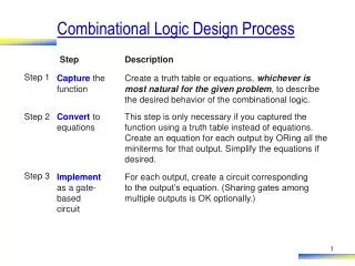
Analysis Procedure • Derivation of Boolean Functions • Derivation of the Truth Table • Logic Simulation
Design Procedure • From the specifications of the circuit, determine the required number of inputs and outputs and assigned a letter symbol to each • Derive the truth table that defined the relationship between inputs and putouts • Obtain the simplified Boolean functions for each output as a function f the input variables • Draw the logic diagram • Verify the correctness of the design
Some Design Examples • BCD to Excess-3 code converter • BCD to Seven Segment Decoder
Decoder Combinational Logic Circuit n Inputs 2n Outputs Decoders • n to 2n decoder - a combinational logic circuit that converts binary information from the n coded inputs to a maximum of 2n unique outputs • Also called the n-to-m line deciders for example: • 2-to-4 line decoder • 3-to-8 line decoder
Decoder Expansion • Can use smaller decoders to build bigger decoders. • e.g. using two 2-4 decoders we can build a 3-8 decoder or using two 3-8 decoders we can build a 4-16 decoder
Combinational Circuit Implementation using Decoder • A n-input decoder generates the minterms corresponding to a boolean function of n-variables • Can use the outputs of a decoder along with an OR gate to implement a Boolean function in SOP form
Encoder Combinational Logic Circuit 2n Inputs n Outputs Encoders • Performs the inverse operation of a decoder • Has 2n or fewer input lines and n output lines • The output generates the binary code corresponding to the input value
Examples of Encoders • Octal to Binary Encoder • Priority Encoder
MULTIPLEXER Combinational Logic Circuit 2n Inputs 1 Output n Selection Lines Multiplexers • A multiplexer is a combinational circuit that selects binary information from one of many input lines and directs the information to a single output line
MULTIPLEXER Combinational Logic Circuit Function table D0 S1 S0 Output D1 4 Inputs Output 0 0 D0 D2 0 1 D1 1 0 D2 D3 1 1 D3 S0 S1 4-to-1-Line Multiplexer
Building MUXes • A MUX can be built using transmission gates • Mutiplexer blocks can be combined in parallel with common selection and enable lines to perform selection on multi-bit quantities
Implementing Boolean Functions Using MUX • Any Boolean function of n-variables can be implemented using a MUX with n selection lines • A more efficient method is using a MUX with n-1 selection lines. • Let us take a look at each method
Demultiplexers • Performs the inverse operation of a multiplexer • A combinational circuit that receives input from a single line and transmits it to one of 2n possible output lines • The selection of the specific output is controlled by the bit combination of n selection lines • Same as a Decoder with an enable – how?