Download
1 / 55
590 likes | 979 Vues
4-1 Introduction The average current in AC source is zero in the full-wave rectifier, thus avoiding problems associated with nonzero average source currents, particularly in transformers. The output of the full-wave rectifier has inherently less ripple than the half-wave rectifier.

E N D
4-1Introduction TheaveragecurrentinACsourceiszerointhefull-waverectifier, thusavoidingproblemsassociatedwithnonzeroaveragesourcecurrents, particularlyintransformers. Theoutputofthefull-waverectifierhasinherentlylessripplethanthehalf-waverectifier. Uncontrolledandcontrolledsingle-phaseandthree-phasefull-waveconvertersusedasrectifiersareanalyzed. CH.4Full-waveandThree- phaserectifiers(ConvertingACtoDC)
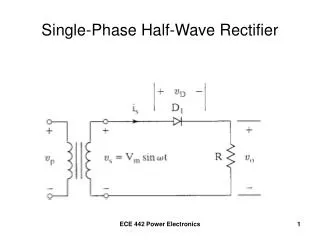
4-2Single-phasefull-waverectifiers Fig.4-1 Bridgerectifier: Thelowerpeakdiodevoltagemakeitmoresuitableforhigh-voltageapplications.
Fig.4-2 center-tappedtransformerrectifier Withelectricalisolation,onlyonediodevoltagedropbetweenthesourceandload, suitableforlow-voltage, high-currentapplications
Resistiveload: powerabsorbedbytheloadresistor: powerfactor :Pf=1
IfLisrelatively large, theloadcurrentisessentiallydc. ( ) Sourceharmonics arerichintheodd-numberedharmonics. Filters:reducingtheharmonics.
Forcontinuouscurrentoperation, theonlymodificationtotheanalysisthatwasdoneforR-LloadisinthedctermoftheFourierseries .Thedccomponentof currentinthiscircuitis. ThesinusoidaltermsintheFourieranalysisareunchangedbythedcsource, providedthatthecurrentis continuous. Discontinuouscurrentisanalyzedlikesection3-5.
Assumingidealdiodes :theanglewherethediodesbecomereversebiased, which isthesameasforthehalf-waverectifierandis =? solvednumericallyfor Peak-to-peakvariation(ripple):
InpracticalcircuitswhereωRC , minimaloutputvoltageoccursat ishalfthatofthehalf-waverectifier.
Fig. 4-7(a) Voltagedoubler Fig. 4-7(b) Dualvoltagerectifier =full-waverectifier(sw.open)+ voltagedoubler(sw.closed)
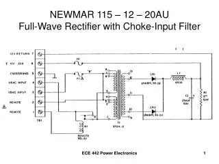
L-Cfilteredoutput: Fig.4-8 C holdstheoutputvoltageataconstantlevel, andtheLsmoothesthecurrentfromrectifierandreducesthepeakcurrentindiodes.
=0 , full-waverectified ContinuousCurrent: Thevariationincanbeestimatefromthefirst Acterm(n=2) intheFourierseries. Theamplitudeoftheinductorcurrentforn=2is where ForContinuouscurrent,
Discontinuouscurrent: Whenispositive ( at ) ,
ProcedurefordeterminingVo: • EstimateaValueforVoslightlybelowVm, andsolve (2) Solvenumerically, (3) Solve (4) SloveVo= (5) Repeatstep(1)~(4) untilthecomputedVoinstep(4) equalstheestimatedVoinstep(1) OutputVoltagefordiscontinuouscurrentislargerthan forcontinuouscurrent.(seeFig4-8(d))
4-3controlledfull-waverectifiers Resistiveload: Fig.4-10
Thepowerdeliveredtotheload Thermscurrentinsourceisthesameasthermscurrentin theload.
discontinuouscurrent : for Fordiscontinuouscurrent Analysisofthecontrolledfull-waverectifieroperatinginthediscontinuouscurrentmodeisidenticaltothatofthecontrolledhalf-waverectifier, exceptthattheperiodfortheoutputcurrentis.
R-LSourceload : Fig.4-14 TheSCRSmaybeturnedonatanytimethattheyareforwardbiased, whichisatanangle
Forcontinuouscurrentcase, theaveragebridgeoutputvoltageis averageloadcurrentis TheacvoltagetermsareunchangedfromthecontrolledrectifierwithanR-Lload. Theaccurrenttermsaredeterminedfromcircuit. Powerabsorbedbythedcvoltageis Powerabsorbedbyresistorintheloadis
ControlledSingle-phaseconverteroperatingasaninverter: seeing Fig4-14. 4-15 .
Forinverteroperation, powerissuppliedbythedcsource, andpowerisabsorbedbythebridgeandistransferredtotheacsystem. VdcandVomustbenegative rectifieroperation inverteroperation
4-4Three-phaserectifiers Resistiveload : Fig4-16
上、下半部Diode,每次僅一個ON;同相上、下Diode不可同時ON;DiodeON由瞬間最大線電壓決定。上、下半部Diode,每次僅一個ON;同相上、下Diode不可同時ON;DiodeON由瞬間最大線電壓決定。 Atransitionofthehighestline-to-linevoltagemusttakeplaceevery . Becauseofthesixtransitionsthatoccurforeachperiodofthesourcevoltage, thecircuitiscalledasix-pulserectifier. vo(t)之基頻為3 電源頻率之6倍 Diode turnoninthesequence1,2,3,4,5,6,1,..
Eachdiodeconductsone-thirdofthetime, resultingin Apparentpowerfromthethree-phasesourceis
Sincetheoutputvoltageisperiodicwithperiod1/6oftheac supplyvoltage, theharmonicsintheoutputareoforder6kω, k=1,2,3,… Adevantage:outputisinherentlylikeadcvoltage, andthehigh-frequencylow-amplitudeharmonicsenablefilterstobeeffective.
whichconsistsoftermsatfundamentalfrequencyoftheacsystemandharmonicsoforder6kwhichconsistsoftermsatfundamentalfrequencyoftheacsystemandharmonicsoforder6k 1, k=1,2,3,… Filters(Fig.4-18) arefrequentlynecessarytopreventharmoniccurrentsto entertheacsystem. Resonantfiltersfor5thand7thharmonics. High-passfiltersforhigherorderharmonics.
Harmonicsforoutputvoltageremainoforder6k, butamplitudearefunctionsof .seeingFig. 4-20
Thepurposeofthetransformerconnectionistointroduce phaseshiftbetweenthesourceandbridge. Thisresultsininputstotwobridgeswhichare apart. Thetwobridgeoutputsaresimilar, butalsoshiftedby . Thedelayanglesforthebridgearetypicallythesame. Thepeakoutputofthetwelve-pulseconverteroccursmidwaybetweenalternatepeaksofthesix-pulseconverters.Addingthevoltagesatthatpointfor gives
SinceatransitionbetweenconductingSCRsevery , thereareatotalof12suchtransitionsforeachperiodoftheacsource. Theoutputhasharmonicfrequencieswhicharemultipleof12timesthesourcefre. (12kk=1,2,…) Cancellation of harmonics 6(2n-1) 1 , n=1, 2, … has resulted from this transformer and converter configuration.
Thisprinciplecanbeexpandedtoarrangementsofhigherpulsenumberbyincorporatingincreasednumberofsix-pulseconverterswithtransformerswhichhavetheappropriatephaseshifts.Thisprinciplecanbeexpandedtoarrangementsofhigherpulsenumberbyincorporatingincreasednumberofsix-pulseconverterswithtransformerswhichhavetheappropriatephaseshifts. Thecharacteristicacharmonicsofap-pulseconverterwillbe pk 1, k=1,2,3… Moreexpenseforproducinghigh-voltage transformerswiththeappropriatephaseshifts.
Three-phaseconverteroperatingasainverter: seeing4-22.
4-6DCpowertransmission ․ Byusingcontrolledtwelve-pulseconverter (generally). ․ Usedforverylongdistancesoftransmissionlines. Advantages:(1) , voltagedrop↓inlines (2) , lineloss ) ( (3) Twoconductorsrequiredratherthanthree (4) Transmissiontowersaresmaller. (5 ) Powerflowinadctransmission lineiscontrollablebyadjustmentofdelayanglesattheterminals. (6) Powerflowcanbemodulatedduringdisturbanceson oneoftheacsystem. Systemstabilityincreased. (7) Thetwoacsystemsthatareconnectedbythedclinedonotneedtobeinsynchronization. Disadvantages:costlyac-dcconverter, filter, andcontrolsystemrequiredateachendofthelinetointerfacewiththeacsystem.
Forcurrentbeingripplefree Powersuppliedbytheconverteratterminal1is Powersuppliedbytheconverteratterminal2is
Fig.4-24usingtwelve-pulseconverter (abipolarscheme)
Oneofthelinesisenergizedatandtheotherisenergizedat - . Inemergencysituations, onepoleofthelinecanoperatewithouttheotherpole, withcurrentreturningthroughthegroundpath.
4-7 commutation :effectofsourceinductance ( ) Single-phasebridgerectifier: Fig.4-25