DIFFERENTIAL POLARIZATION DELAY LINE Controller FINAL REPORT
This final report presents the design and implementation of a digital control system for a Differential Polarization Delay Line (DDL) at the Technion Institute of Technology. The project aims to achieve precise control over the delay between two orthogonal polarizations of light traveling through a fiber, with a delay range of ±50 picoseconds and a resolution of 0.0017 picoseconds. The controller utilizes a PID algorithm, incorporating both a graphical user interface for interactive use and a command line for automation. The report also discusses hardware components, system requirements, and future improvements for enhanced performance.

DIFFERENTIAL POLARIZATION DELAY LINE Controller FINAL REPORT
E N D
Presentation Transcript
Technion – Israel Institute of Technology Department of Electrical Engineering High Speed Digital Systems Lab DIFFERENTIAL POLARIZATION DELAY LINE ControllerFINAL REPORT D0215 Supervisor : Mony Orbach Performed by: Maria Terushkin Guy Ovadia
Project Goals The ultimate goal of the project is providing digital control for the DDL
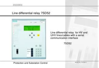
DDL overview • splits light within a fiber into orthogonal polarizations • actively varies the time that one polarization travels compared to the other polarization • combines the two polarizations together again • Delay range ±50psec • Delay Resolution 0.0017 pSec
Tunable laser source PC optical spectrum analyzer DDL controller Function generator Manual control Project Description • Previous usage of the DDL • Current usage of the DDL
The world as we see it • DDL contains: • DC brush motor • Encoder • Limit switches -50 0 +50
PC controller DDL Controller IOs • Inputs: • Encoder signals A,B • Limit indicators • Commands from PC (via USB) • Output: • PWM varying duty-cycle • Reports to PC (via USB) PWM USB Encoder feedback + limits
System requirements • Maximal travel beyond the home/end indications – 2mm • Steady state error – not greater than a single encoder count • No cumulative positional error • Up to 3 sec convergence to the required set point after reaching it • No closed loop control after reaching desired position
I + + - P Plant D Theoretical background • Digital PID • Continuous time domain • Discrete time domain • Where
Implementation • Hardware • MMC (PCB) + Driver (wire-wrap board) • FPGA Logic • PID algorithm • Communication with PC via DLP • Software • GUI • Command line interface
H bridge HIP4020 Power management Power management Hardware overview DLP USB245M transceiver Altera Cyclone transceiver transceiver wire-wrap MMC
Limit protection Synchronization Debouncing Filtering Of signals Position Decoding PID homing Communication FPGA logic overview mux PWM Duty-cycle Main Controller Control lines to all blocks
Application Software • Two versions: • GUI version for interactive use • Command line version for automation • Both versions save the last known delay, and load it on controller power-up.
GUI Application commands • User commands • Set delay • Redefine current delay • Immediate stop • Service commands • Manual PWM override + direction control • PID constants calibration • Initiate Homing procedure • Record internal data
Command line application • Contains a subset of commands useful for automation • Set delay (in pSec or encoder counts) • Load windup constant (controls speed) Compatible with VEE Pro and Matlab
Discussion and conclusions • Meeting system requirements Position vs. Time go to 10 pSec 12121 encoder counts
Discussion and conclusions cont. • Use of a model: • Differences between the model and the DDL and their consequences • Use of work previously done in the lab – pros and cons. • Power up • Chip safety • Implementation alternatives • Microcontroller
What’s next ? • Algorithm improvement / additional features • Trajectory planning • Dual loop (velocity control) • Notch filter (mechanical resonance) • Backlash compensation algorithm • User defined software limits • Hardware improvement • Custom PCB, no wire-wrap • Tighter integration with the equipment at the EO lab • Automatic zero detection / calibration
Demonstration – EO lab. • Short demonstration: • Homing procedure • “go to” 20 pSec delay position • Return to 10 pSec • Find zero manually and set it there • Power off the controller • Turn back on – last known position is retrieved
The enD Just follow the yellow optical fiber ! (to the land of OZ optics)