Download
1 / 33
330 likes | 521 Vues
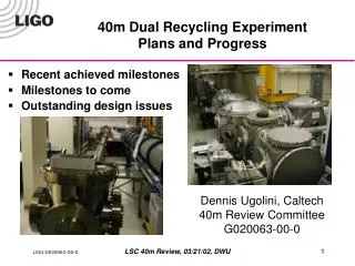
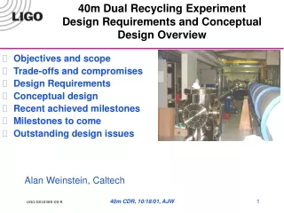
40m Dual Recycling Experiment Design Requirements and Conceptual Design Overview. Objectives and scope Trade-offs and compromises Design Requirements Conceptual design Recent achieved milestones Milestones to come Outstanding design issues. Alan Weinstein, Caltech. People.

E N D
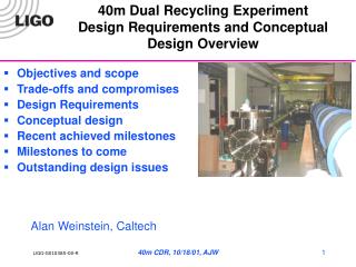
40m Dual Recycling ExperimentDesign Requirements and Conceptual Design Overview • Objectives and scope • Trade-offs and compromises • Design Requirements • Conceptual design • Recent achieved milestones • Milestones to come • Outstanding design issues Alan Weinstein, Caltech 40m CDR, 10/18/01, AJW
People • Live & breathe 40m: Alan Weinstein, Dennis Ugolini, Steve Vass, Ben Abbott • LIGO lab engineers playing major roles: Garilynn Billingsley, Lisa Bogue, Rolf Bork, Lee Cardenas, Dennis Coyne, Jay Heefner, Larry Jones, Rick Karwoski, Peter King, Janeen Romie, Paul Russel, Mike Smith, Larry Wallace • Lots of SURF students (this summer – 6) and visitors. • We’ll need lots of add’l help in coming years! 40m CDR, 10/18/01, AJW
40m Laboratory Upgrade - Objectives • Primary objective: full engineering prototype of optics control scheme for a dual recycling suspended mass IFO, Looking as close as possible to the Advanced LIGO optical configuration and control system Advanced LIGO optical configuration • Key features: • Pre-stabilized laser • Frontal modulation • Input mode cleaner • Power- and Signal-recycled Michelson • High finesse Fabry-Perot arms • Detuned signal cavity • Output mode cleaner • DC readout of GW signal 40m CDR, 10/18/01, AJW
Timeline • Table-top IFOs at Caltech, Florida, Australia, Japan (~ complete!) • These lead to decision on control scheme by LSC/AIC (August 2000 LSC) • Glasgow 10m DR prototype with multiple pendulum suspensions (2002) • Then, full LIGO engineering prototype of ISC, CDS at 40m (2003-2004) • First look at DR lock acquisition, response function, shot noise response (high-f) 40m CDR, 10/18/01, AJW
Advanced LIGO technical innovations tested at 40m • a seventh mirror for signal recycling • (length control goes from 4x4 to 5x5 MIMO) • detuned signal cavity (carrier off resonance) • pair of phase-modulated RF sidebands • frequencies made as low and as high as is practically possible • unbalanced: only one sideband in a pair is used • double demodulation to produce error signals • short output mode cleaner • filter out all RF sidebands and higher-order transverse modes • offset-locked arms • controlled amount of arm-filtered carrier light exits asym port of BS • DC readout of the gravitational wave signal Much effort to ensure high fidelity between 40m and Adv.LIGO! 40m CDR, 10/18/01, AJW
Differences between AdvLIGO and 40m prototype • Initially, LIGO-I single pendulum suspensions will be used • Full-scale AdvLIGO multiple pendulums will not fit in vacuum chambers • to be tested at LASTI • Scaled-down versions can fit, to test controls hierarchy – in 2004? • Only commercial active seismic isolation • STACIS isolators already in use on all 4 test chambers • providing ~30 dB of isolation in 1-100 Hz range • No room for anything like full AdvLIGO design – to be tested at LASTI • LIGO-I 10-watt laser, negligible thermal effects • Other facilities will test high-power laser: LASTI, Gingin, … • Thermal compensation also tested elsewhere • Small (5 mm) beam spot at TM’s; stable arm cavities • AdvLIGO will have 6 cm beam spots, using less stable cavities • 40m can move to less stable arm cavities if deemed useful • Arm cavity finesse at 40m chosen to be = to AdvLIGO • Storage time is x100 shorter • significant differences in lock acquisition dynamics, in predictable ways • Due to shorter PRC length, control RF sidebands are 36/180 MHz instead of 9/180 MHz; less contrast between PRC and SRC signals 40m CDR, 10/18/01, AJW
40m Laboratory Upgrade – More Objectives • Expose shot noise curve, dip at tuned frequency • Multiple pendulum suspensions • this may be necessary, to extrapolate experience gained at 40m on control of optics, to LIGO-II • For testing of mult-suspension controllers, mult-suspension mechanical prototypes, interaction with control system • Not full scale. Insufficient head room in chambers. • Won’t replace full-scale LASTI tests. • thermal noise measurements • Mirror Brownian noise will dominate above 100 Hz. • Facility for testing/staging small LIGO innovations • Hands-on training of new IFO physicists! • Public tours (SURF/REU students, DNC media, princes, etc) 40m CDR, 10/18/01, AJW
Design Requirements • The optical configuration of the 40m IFO should be a power- and signal recycled Michelson with Fabry-Perot arms. • The optical configuration should emulate, as closely as possible, that of Advanced LIGO. Any significant differences (impacting lock acquisition and control) should be well understood. • The interferometer controls, diagnostics, and monitoring must be adequate to the task of bringing and keeping the interferometer in lock. • The interferometer must be able to be brought into lock (including all length and angular degrees of freedom), with locking times on the order of seconds, and remain robustly in-lock for hours. • The DC circulating beam power in all cavities, and in all beam frequency components, and at all stages of lock acquisition, should be within expectations from models • The in-lock GW response function should be measureable, and measured to be within expectations from models • The ability to control the DOFs unique to Advanced LIGO (SRC length, SRM pitch and yaw, peak in response function due to SRC detuning, offset-locking of the arms, DC readout of the L_ degree of freedom, etc) without degrading the control of the Initial LIGO degrees of freedom, should be demonstrated. 40m CDR, 10/18/01, AJW
More design requirements • Sources of noise which impact the ability of the interferometer to obtain and maintain lock must be identified, and efforts must be made to eliminate them • Best efforts must be made to reduce those sources of noise that contribute to the GW readout, especially in the high-frequency (shot-noise-limited) regime • Systems must be in place to monitor and reduce excess noise from the usual sources: electronics, EM pickup, scattered light, vacuum pressure, seismic motion, suspensions & controllers, misalignments, mode mismatch, etc… • Data logged to Frames for offline analysis • The laboratory must be a safe environment in which to work 40m CDR, 10/18/01, AJW
Conceptual design • 40m upgrade conceptual design report (T010115) is available • Optical systems DRD and CDR (T010117) is available • Optical topology (Dual recycled Michelson with F-P arms) (AJW) • Infrastructure upgrade (Larry Jones) • Suspended optics (GariLynn Billingsley) • Suspensions (Janeen Romie) • Suspension controllers (Ben Abbott) • Laboratory subsystems (PSL, DAQ, PEM, Vacuum, etc) (Dennis Ugolini) Optical systems and sensing design (Mike Smith) • Auxiliary optical systems, scattered light control, … (Mike Smith) • Outstanding issues (AJW) 40m CDR, 10/18/01, AJW
40m Infrastructure – substantially complete • Dismantling of old IFO, distribution of surplus equipment to LIGO and LSC colleagues • Major building rehab: • IFO hall enlarged for optics tables and electronics racks • roof repaired, leaks sealed • new electrical feeds and conditioners, 12" cable trays, etc • new control room and physicist work/lab space • New entrance room/changing area • rehab of cranes, safety equipment, etc • Active seismic isolation system (STACIS) procured, installed, and commissioned on all four test mass chambers 40m CDR, 10/18/01, AJW
40m Infrastructure, continued • New vacuum control system and vacuum equipment • Installed and commissioned • New output optic chamber, seismic stack fabricated • Chamber installed in July, stack to be installed in fall 2001 • Vacuum envelope for 12 m input mode cleaner fabricated • Chamber installed in July, stack to be installed in fall 2001 • All electronics racks, crates, cable trays, computers, network… procured and installed • New optical tables 40m CDR, 10/18/01, AJW
New vacuum envelope at 40m New Output Optic Chamber PSL Electronics PSL Enclosure Cable trays BS chamber New optical tables 12m MC beamtube 40m CDR, 10/18/01, AJW
Lab Infrastructure systems • DAQS • PEM • PSL • Seismic stacks • STACIS • Vacuum equipment and controls • Computing, networking • Laser Safety • In-vacuum cables • Vacuum envelope • Optical tables Dennis Ugolini, Steve Vass, Ben Abbott Larry Jones, Steve Vass 40m CDR, 10/18/01, AJW
40m PSL • LIGO-I PSL installed in June by Peter King, Lee Cardenas, Rick Karwoski, Paul Russell • Spent the last month fixing birthing problems, tuning up (Ugolini, Ben Abbott, SURF students) • All optical paths have had one round of mode matching tune-up, comparing BeamScan with model; round 2 coming up. • Frequency stability servo (FSS) and PMC servo (PMCS) have been debugged • Both servos now lock easily, reliably, stably • DAQ birthing problems have been fixed; full DAQ readout of fast channels (and slow EPICS channels) logged to frames routinely • Frequency reference cavity has visibility > 94%; PMC has visibility ~80% and transmission > 50%. More tuning required, and Peter will install less lossy curved mirror sometime soon. • No temp stability on Freq reference cavity; Peter should have heating jacket on order. • Full characterization of PSL in progress, first draft available within a month: • Frequency noise • Intensity noise • Pointing and angle jitter • Long-term stability of frequency, intensity, pos/angle • Beam size and mode matching everywhere on table. 40m CDR, 10/18/01, AJW
Optical design • Dual recycled Michelson with F-P arms. Specified: • 12m Input Mode Cleaner design, expected performance • Core mirror dimensions (3”x1” for all optics except for 5”x2” TMs) • transmissivities, cavity finesses, gains, pole frequencies • Cavity lengths, RF frequencies, resonance conditions • Mirror ROC, beam dimensions everywhere • SRC tune specified, transfer function determined • DC detection scheme • Twiddle modeling, DC fields, length sensing matrix • ModalModel, alignment sensing matrix, WFS parameters (TBD) • Expected noise (BENCH) • Thermal effects – estimated to be negligible 40m CDR, 10/18/01, AJW
Optics parameters ETM 40m upgrade optical layout AJW, 8/2001. MMTs obsolete. 5.242 57.375 Optical Lengths (mm) Beam Amplitude Radius (mm) Beam Radius of Curvature (m) 38,250 3.027 flat ITM Vacuum MMT MC ETM RM ITM MMT RF 1,602 PSL 174 149 1000 180 1450 927 1,145 300 2,025 38,250 BS 12,680 3.033 412 3.05 174 0.99 1.16 5.242 57.375 1.658 731 1.658 731 3.036 348 3.027 flat 200 0.371 flat 3.038 365 1.67 64 3.036 239 1.66 40 1.657 flat 3.076 17.869 SM • Arms are half-symmetric, g = 1/3 • Beams are w0 ~ 3 mm everywhere in vertex area • IMC almost identical to Initial LIGO LLO4K • Mode matching done in detail by M. Smith • (PSL FRC, PSL PMC, PSL IMC, IMC IFO, IFO OMC, output beams sensors) 40m CDR, 10/18/01, AJW
Optical Layout Mike Smith • All suspended optics have OpLevs and are in sight of cameras • Almost all of 9 output beams come out in this area, routed to ISC tables • 12m input mode cleaner • short monolithic output MC • baffling, shutters, scattered light control • Mode matching between each optical system • integrated with building, electrical, CDS layout • Detailed layout of all ISC tables, with detailed parts lists 40m CDR, 10/18/01, AJW
Optical Layout Baffles, isolators, Shutters, etc 40m CDR, 10/18/01, AJW
Detailed layouts of ISC tables, parts lists 40m CDR, 10/18/01, AJW
Suspended optics • Ten suspended optics • MCF1, MCF2, MCCM, PRM, SRM, BS, ITMx, ITMy, ETMx, ETMy • All suspended optics blanks are in hand (more spares on order) • Polishing, coating in progress – GariLynn • All SOS suspensions (6+spare) in hand – Janeen • Scaled SOS suspensions for test masses under construction – Janeen • Digital suspension controllers under design – Ben Abbott, Jay Heefner 40m CDR, 10/18/01, AJW
Control topology for Advanced LIGO ETMperp Carrier RF Sidebands f1 RF Sidebands f2 ITMperp Input ITMinline ETMinline Symm Port PRM Pickoff SRM Asym Port 40m CDR, 10/18/01, AJW
GW RF, DC fields, and LSC signals – from Twiddle GW Response Function Michelson ( l-) signal is sub-dominant everywhere. 40m CDR, 10/18/01, AJW
AdvLIGO and 40m noise curves 40m AdvLIGO (PF, 7/01) 40m CDR, 10/18/01, AJW
Milestones achieved so far • Old IFO dismantled, surplus equipment distributed • Lab infrastructure substantially complete, incl new conditioned power, new 12” cable trays, new CDS racks • Vacuum control system complete (D. Ugolini) • Active seismic isolation system installed, commissioned (Vass, Jones, etc) • Vacuum envelope for 12m MC and output optic chamber installed (Vass, Jones) • All but one optical table in place (Vass, Jones) • Remaining on infrastructure: install seismic stacks for 12m MC and OOC; all in-vacuum cabling; and one more (big) optical table. • DAQ system installed, logs frames continuously (R. Bork) • PSL installed, commissioned; full tuning and characterization in progress (P. King, L. Cardenas, R. Karwoski, P. Russell, D. Ugolini, B. Abbott, SURFs) • Many PEM devices installed, in EPICS and DAQS, and in routine use (vacuum gauges, weather station, dust monitor, STACIS, accelerometer, mics, …) (Ugolini, SURF Tsai). 40m CDR, 10/18/01, AJW
More milestones achieved • Full in-vacuum optical layout complete, incl. Mode matching and steering, optical levers, cameras (M. Smith) • Full out-of-vacuum IFO sensing table layout complete, for 11 output beams; parts lists assembled (M. Smith) • Scattered light control, baffling, isolators (M. Smith) • Design of digital suspension controllers for MC and COC in progress (B.Abbott, J.Heefner) • Computing hardware, networking, software (EPICS, Dataviewer, DMT, etc) largely in place (Bork, Ugolini, Bogue, Wallace) • Optical glass in hand, polishing of MC glass in progress (G. Billingsley) • Specs for polishing and coating core optics ready (G. Billingsley) • SOS suspensions (all but TM’s) constructed (J. Romie) • TM suspensions designed and in construction (J. Romie) • Detailed WBS for construction, and for experiment (T. Frey) 40m CDR, 10/18/01, AJW
Milestones through 2002 • 4Q 2001: Infrastructure complete • PSL, 12m MC envelope, vacuum controls, DAQS, PEM. • Conceptual design review. Begin procurement of CDS, ISC, etc. • 2Q 2002: • All in-vacuum cables, feedthroughs, viewports, seismic stacks installed. • 12m input MC optics and suspensions, and suspension controllers. • 3Q 2002: • Begin commissioning of 12m input mode cleaner. • Acquisition of most of CDS, ISC, LSC, ASC. • 4Q 2002: • Core optics (early) and suspensions ready. Ten Suspension controllers. Some ISC. • Glasgow 10m experiment informs 40m program • Control system finalized 40m CDR, 10/18/01, AJW
Milestones through 2004 • 2Q 2003: • Core optics (late) and suspensions ready. • auxiliary optics, IFO sensing and control systems assembled. • 3Q 2003: Core subsystems commissioned, begin experiments • Lock acquisition with all 5 length dof's, 2x6 angular dof's • measure transfer functions, noise • Inform CDS of required modifications • 3Q 2004: Next round of experiments. • DC readout. Multiple pendulum suspensions? • Final report to LIGO Lab. 40m CDR, 10/18/01, AJW
(Some) outstanding issues and action items (40m, AdvLIGO) • Any significant changes in people’s thinking re: optical configuration, controls, CDS architecture?? • Near term: in addition to the digital suspension controllers, need LSC and ASC for input mode cleaner, and servos for steering PSL beam into input mode cleaner and thence into IFO. • Develop ASC model with ModalModel. • IFO design (optics, sensing, control, etc) needs careful review by experts, double-check LSC, ASC calculations – I welcome volunteers!! • 180 MHz PD’s for WFS, LSC. Double demodulation(180 36 MHz). • Design servo filters for LSC, ASC! • Detailed noise model (RSENOISE, Jim Mason) • Lock acquisition studies with E2E/DRLIGO. Develop lock acquisition algorithms, software. • Triple-check thermal effects (Melody) – negligible? • Output mode cleaner – will PSL-PMC-like device be adequate? (For 40m, for AdvLIGO). Suspended? • Offset-lock arms - algorithms, software. • DC GW PD – in vacuum? Suspended? 40m CDR, 10/18/01, AJW