Direct Readout Lab Roadmap to NPP and Beyond
340 likes | 523 Vues
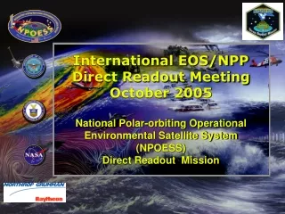
International EOS/NPP Direct Readout Meeting October 2005 National Polar-orbiting Operational Environmental Satellite System (NPOESS) Direct Readout Mission. Direct Readout Lab Roadmap to NPP and Beyond. Data Volume Evolution. 1960 - 2010. 2000 - 2010. 2010 – 2020+.

Direct Readout Lab Roadmap to NPP and Beyond
E N D
Presentation Transcript
International EOS/NPP Direct Readout MeetingOctober 2005National Polar-orbiting Operational Environmental Satellite System(NPOESS)Direct Readout Mission
Data Volume Evolution 1960 - 2010 2000 - 2010 2010 – 2020+ NPP(NPOESS Preparatory Project) NPOESS (National Polar-orbiting Operational Environmental Satellite System) DMSP(Defense Meteorological Satellite Program) POES(Polar Orbiting Operational Environmental Satellites) EOS (Earth Observing System) Sensor data rate: 1.5 Mbps Data latency: 100-150 min. 1.7 GigaBytes per day (DMSP) 6.3GigaBytes per day (POES) 15 Mbps sensor data rate Data latency: 100-180 min. Data availability: 98% Ground revisit time: 12 hrs. 2.6 TeraBytes per day (EOS) 2.4 TeraBytes per day (NPP) 20 Mbps sensor data rate Data latency: 28 min. Data availability: 99.98% Autonomy capability: 60 days Selective encryption/deniability Ground revisit time: 4-6 hrs. 8.1 TeraBytes per day NPOESS Satisfies Evolutionary Program Needs with Enhanced Capabilities
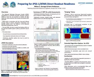
RF Communications Subsystem Overview • SafetyNet SMD Downlink • Ka-band, biaxial steerable spacecraft antenna • High rate mission data and real-time and/or stored telemetry provided with low latency worldwide • Command • S-band, omni antenna • Encryption/Authentication • Telemetry • S-band, omni antenna • TDRS • LEO&A • On-orbit backup • HRD • X-band, earth coverage spacecraft antenna • Channel rate of 40 Mbps • LRD • L-band, earth coverage spacecraft antenna • Channel rate at 7.76 Mbps • Command and Uploads • S-band, omni antenna • Encryption/Authentication • Telemetry • S-band, omni antenna • Both real-time and stored telemetry channels DRR Wideband ground communications HRD FTS Sites • Svalbard, Norway • Primary T&C LRD FTS Sites C3S
Overview Spacecraft Iso-view S-band Antenna (Zenith) CMIS Antenna Unit VIIRS SARSAT/ADCS Antenna-Rx Altimeter CRIMSS SESS HORUS TSIS ADCS Antenna-Tx S-band Antenna (Nadir) ATMS CRIS HRD Antenna NPOESS Spacecraft (1730 Orbit Shown) SARSAT Antenna-Tx LRD Antenna
HRD EIRP vs. Nadir Angle • Shaped beam antenna compensates for space & rain loss variation (function of ground antenna elevation angle) to provide near constant PFD at surface of Earth
HRD Downlink Spectral Mask • SRRC pulse shaping provides bandwidth efficient spectral occupancy
HRD Long-Term Orbit-Averaged Availability • Orbit-Average availability over any short-term period may be different than long-term average
LRD EIRP vs. Nadir Angle • Shaped beam antenna compensates for space and rain loss Variation (function of ground antenna elevation angle) to provide near constant PFD at surface of Earth
LRD Downlink Spectral Mask • SRRC pulse shaping provides bandwidth efficient spectral occupancy
LRD Long-Term Orbit-Averaged Availability • Orbit-Average availability over any short-term period may be different than long-term average
NPOESS / NPP Sensor Manifest 1330 - NPOESS 1730 - NPOESS 2130 - NPOESS 1030 - NPP VIIRS VIIRS VIIRS VIIRS CMIS CMIS CMIS CrIS CrIS CrIS ATMS ATMS ATMS SESS SESS SESS SS SS SS SARSAT SARSAT SARSAT ADCS ADCS CERES ERBS OMPS OMPS ALT APS TSIS
LRD Data Content Balances Performance and Provides Flexibility 3.88 Mbps Limited LRD Bandwidth Selection of compression (6:1) applied to selected VIIRS mission data for increased mission data throughput in downlink 1330 & 1730 2130 VIIRS CMIS CrIS Programmable LRD downlink provides flexibility for the future
Field Terminal Ancillary Data Approach • Dynamic ancillary data contained within LRD and HRD downlinks to meet specified performance levels • Data for six pressure levels from the NWP forecast model • Temperature • Humidity • Surface pressure • Standard pressure levels • Wind speed, wind direction • Precipitable water • For SESS EDR production • Effective sunspot number and global geomagnetic Kp • NPOESS mission support data server, accessible via internet
Ancillary Data DownlinkGraphical Representations • 16 points spaced 200 kilometers apart at right angles to the ground track • Completely covers the area viewed by all sensors • Successive lines 200 kilometers apart • Each line transmitted twice to ensure receipt by the ground Path of the satellite
NPOESS High Rate Data (HRD)Environmental Data Records (EDRs) VIIRS CMIS CrIS/ATMS OMPS SES GPSOS ERBS TSIS ALT APS 25 19 3 1 13 2 5 1 3 4 EDRs with Key Performance Parameters Ozone; Total Column/Profile Atm Vertical Temp Profile Cloud Top Height Atm Vertical Moisture Profile Cloud Top Pressure Precipitable Water Precipitation Type/Rate Cloud Top Temperature Sea Surface Temperature Sea Surface Winds Downward LW Radiance (Sfc) Pressure (Surface/Profile) Soil Moisture Downward SW Radiance(Sfc) Sea Ice Characterization Imagery Electric Field Sea Surface Height/Topo. Electron Density Profile Snow Cover/Depth Active Fires Aerosol Optical Thickness Energetic Ions Solar Irradiance Aerosol Particle Size Geomagnetic Field Supra-Thermal-Auroral Part. Aerosol Refractive Index Ice Surface Temperature Surface Type Surface Wind Stress Albedo (Surface) In-situ Plasma Fluctuations Auroral Boundary In-situ Plasma Temperature Suspended Matter Ionospheric Scintillation Auroral Energy Deposition Total Water Content Auroral Imagery Medium Energy Charged Particles Vegetation Index Cloud Base Height Land Surface Temperature Cloud Cover/Layers Net Heat Flux Cloud Effective Particle Size Net Solar Radiation (TOA) Cloud Ice Water Path Neutral Density Profile Cloud Liquid Water Ocean Color/Chlorophyll Cloud Optical Thickness Ocean Wave Characteristics Cloud Particle Size/Distribution Outgoing LW Radiation (TOA)
NPOESS Low Rate Data (LRD)Environmental Data Records (EDRs) VIIRS CMIS CrIS/ATMS OMPS SES GPSOS ERBS TSIS ALT APS 25 19 3 1 13 2 5 1 3 4 EDRs with Key Performance Parameters Ozone; Total Column/Profile Atm Vertical Temp Profile #2 Cloud Top Height Atm Vertical Moisture Profile #3 Cloud Top Pressure (P) Precipitable Water Precipitation Type/Rate Cloud Top Temperature Sea Surface Temperature #8 Sea Surface Winds #4 Downward LW Radiance (Sfc) Pressure (Surface/Profile) #7 Soil Moisture Downward SW Radiance(Sfc) Sea Ice Characterization Imagery #1 Electric Field Sea Surface Height/Topo. Electron Density Profile Snow Cover/Depth Active Fires (P) Aerosol Optical Thickness Energetic Ions Solar Irradiance Aerosol Particle Size Geomagnetic Field Supra-Thermal-Auroral Part. Aerosol Refractive Index Ice Surface Temperature Surface Type (P) Surface Wind Stress Albedo (Surface) In-situ Plasma Fluctuations Auroral Boundary In-situ Plasma Temperature Suspended Matter Ionospheric Scintillation Auroral Energy Deposition Total Water Content Auroral Imagery Medium Energy Charged Particles Vegetation Index (P) Cloud Base Height #5 Land Surface Temperature Cloud Cover/Layers #6 Net Heat Flux Cloud Effective Particle Size Net Solar Radiation (TOA) Cloud Ice Water Path (P) Neutral Density Profile Cloud Liquid Water Ocean Color/Chlorophyll Cloud Optical Thickness Ocean Wave Characteristics Cloud Particle Size/Distribution Outgoing LW Radiation (TOA)
Open Systems Group standards compliance at interfaces minimizes configurations Programmable LRD downlink favors 8 Priority EDRs Onboard VIIRS data compression rates by APID for LRD Flexible ancillary data approach Dynamic ancillary data via satellite downlink NPOESS Mission Support Data Server via Internet access Field Terminal Data Processor Element Software Design
HRD EDR performance 99% of performance attributes meet or exceed performance thresholds Latency requirements achievable with current COTS multiple CPU workstations Designed to recognize missing channels and ancillary data Lossless RICE compression on VIIRS LRD EDR performance 0.8 km resolution imagery and programmable downlink Produces 8 high priority EDRs at or near LRD objective levels Produces 15 lower priority EDRs and required predecessor EDRs Designed to recognize missing channels and ancillary data Lossless and Lossy JPEG2000 compression on selected APIDs FTS EDR Performance
FTS Latency Requirement: max latency is 15 minutes. SYS013235 & SYS013230 - Field Terminal software, when installed on NPOESS-specified HRD field terminal hardware, shall produce the Imagery EDR in less than or equal to 2 minutes and all other EDRs as specified in Appendix E in less than or equal to 15 minutes after receipt of data from the FT Signal Processing Subsystem. A large number of factors impact FTS processing. Terrain - Land or ocean Day versus Night sensor characteristics Weather - Cloudy, Partial Cloudy, Clear Satellite Orbits & FTS emplacement (Latitudes) FTS Hardware: CPUs (3 GHz NPP era) FTS Latency Analysis for Stress-case
FTS Simulation (e.g. 45N/00):1 day 15 Passes with 3 NPOESS S/C Contact Durations: Max 13.1 mins Avg 10.5 mins Min 2 mins <4mins 2.3% 133017302130 FTS Contacts with NPOESS S/C (1440 minutes = 1 days) Back-to-back contacts
Back-to-back S/C Contacts Gap Time Between Contacts Max gap is 2.1 orbits at equator Analyzed STK 1330/1730/2130 contact data • Overlapping S/C contacts don’t occur due to spacecraft orbital phasing. • Smallest gap of 10.2 minutes has minimal impact to FTS latency. • Above 60N there is a large increase in contacts and EDRs. 60N
Orbital Position Defines Dynamic Scene Content in Sensor Data Scene in VIIRS View Ocean Cloudy Snow/Ice Orbital Position defines Sensor Nadir NCEP Weather Data Base Dynamic Processing
Land has process loads comparable to ocean. Day data is 4x night data processing. Day-only algorithms are: ACO/OCC Vegetation Index Surface Types Aerosols (large load) Surface Albedo (large load) Clear Data is most stressing Clear-only algorithms are: ACO/OCC Vegetation Index Land/Ice Surface & Sea Surface Temp Surface Types Aerosols (large load) Surface Albedo (large load) CMIS/CrIS AVT/MP (large load) Used Land, Day and 100% Clear data Land/Ocean, Day/Night, and Clear/Cloudy Data EDR Processing Day Night EDR Processing
FTS Latency StatusAll EDRs & Imagery EDR • Comparison of 2.6 GHz and 5.0 GHz HRD Results
NPOESS Field Terminal Segment Schedule Build 1.2 Build 1.3 Build 1.4 Build 2.1 Build 2.2 Build 2.3 FT NPOESS FTTS, ICD & FTDS CDR Version Apr 2006 FT NPOESS ICD PDR Version Apr 2005 FTS 2.2 S/W Release Oct 2008 Tech Specs PDR Version May 2005 FTS FAT Build 2.3 April 2009 FTS FAT 2.2 Sept 2008 FTS 2.3 S/W Final Release June 2009 2005 2006 2008 2009 2004 2007 2010 NPP Ground Readiness Jul 2007 NPP HRD Demo NLT April 2009 NPOESS C1 Launch Jul 2010 IDPS FAT 2.3 Feb 2009 IDPS FAT Build 2.2 May 2008 PDA Mar 2005 PDR Jun 2005 NPP Launch April 2008
Direct Readout Mission POCs: John Overton: (301) 713-4747 Bill Munley: (301) 713-4782 Joe Mulligan: (301) 713-4803 John van de Wouw: (310) 812-0800 NPOESS websites Http://www.npoess.noaa.Gov Http://npoesslib.ipo.noaa.Gov/ (electronic bulletin board) NPOESS Direct Readout Mission Points of Contact