Download
1 / 12
120 likes | 361 Vues
LTU & Electron Beam Dump Tim Montagne, LCLS Linac December 12, 2003. LCLS Coordinate System LTU Design Overview Electron Beam Dump Design Overview Design Risk . LCLS Coordinate System. The coordinate system will be defined in LCLS Technical Note LCLS-TN-03-8.

E N D
LTU & Electron Beam Dump Tim Montagne, LCLS Linac December 12, 2003 • LCLS Coordinate System • LTU Design Overview • Electron Beam Dump Design Overview • Design Risk Tim Montagne
LCLS Coordinate System The coordinate system will be defined in LCLS Technical Note LCLS-TN-03-8. The coordinate system is defined relative to the Linac coordinate system. Tim Montagne
CD1 DL2 Becomes LTU • CD1 DL2 to LTU Design Comparison • The DL2 design was changed to allow expansion of LCLS into multiple beamlines. • CD1 DL2 Design • The CD1 DL2 design allowed for 2 beamlines, North and South. • The original DL2 length was 65.5m . • LTU Design • The present LTU design allows for 5 beamlines. • The LTU length is 293.3 m. Tim Montagne
LTU Future Expansion with New Undulator Lines 113 Future + 4 ºSoft X-ray Line Future +2 ºline research yard (FFTB) Undulator Start 2nd FEL Line North ~1.5º spont. und. 1st FEL Line South 4 m Future -2ºline Tim Montagne
LTU Design Overview • LTU Design Layout • The LTU beamline device layout is generated automatically using MAD deck coordinates. • Beamline Devices • Known device models are used for defined assemblies. • Placeholder objects are used for undefined designs. Tim Montagne
LTU Design Overview – Magnet Support Concept • LTU Magnet Support • The quadrupole and X-Y corrector pair are mounted on a high stiffness modular support weldment. Tim Montagne
LTU Design Overview – Magnet Support Concept • LTU Magnet Support • The quadrupole and X-Y corrector pair are mounted on a high stiffness modular support weldment. • Support Installation • Each support pad will be installed and aligned prior to support installation. • This arrangement was used in PEP-II and Spear 3. Tim Montagne
LTU Vacuum System Design • Vacuum System Design • Optimized conductance. • Drift tubes <16 RMS finish. • Drift tube material high electrical conductivity. • Vacuum sector length optimized for short pumpdown time during service. Tim Montagne
LTU Device Summary • 37x .91Q17.72 quadrupole magnet • 4x 4D102.36 dipole magnet • 22x X corrector magnet • 22x Y corrector magnet • 2x Y bend magnet (transition BSY to LTU) • 38x stripline typeBPM • 8x RF BPM • 3x X collimator • 3x Y collimator • 2x Energy Collimator • 3x Bunch length monitor • 1x Single beam kicker magnet and dump • 4x Wire scanner • 3x Toroid • 1x CSR Bunch Length Monitor • 1x OTR Bunch Length Monitor • 2x OTR Profile Monitor Tim Montagne
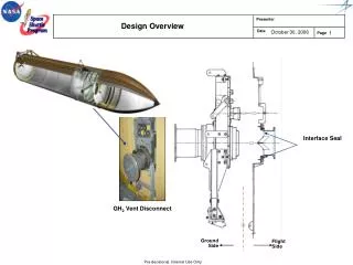
Electron Beam Dump Design Overview • Electron Beam Dump Design • The dump layout is automatically positioned using MAD deck coordinates. • Radiation Physics • The beam dump design is in review by radiation physics. Dipole Bend Magnet Safety Bend Magnet X-Ray Line Electron Beam Beam Dump Tim Montagne
Electron Beam Dump Device Summary • 1x 4D102.36 dipoles • 2x Stripline type BPM • 3x .91Q17.72 quadrupoles • 2x X collimator • 3x Y collimator • 2x Y safety Y bend magnet • 1x Profile monitor • 4x Y bend magnet • 1x Beam dump Tim Montagne
Design Risk • Low Risk Designs • Quadrupole Magnets • Dipole Magnets • Corrector Magnets • BPMs • Toroids • Collimators • Tune up Dumps • Alignment Stages • Supporting Structures • Vacuum System • Medium Risk Designs • Polished, High Electrical Conductivity Vacuum Chambers • Wire Scanners • OTR Profile Monitor • High Risk Designs • Electro-Optical Bunch Length monitor • CSR Bunch Length Monitor • OTR Bunch Length Monitor • RF BPM Tim Montagne