Beam Steering Tools
Beam Steering Tools. J örg Wenninger for the steering & feedback team: R. Steinhagen, G.Sivatsky, JW Acknowledgements to the usual BI friends, L. Jensen & R. Jones. ‘Slow’ Steering Application overview Threading Calibration & K-modulation Tools Orbit feedback Status & plans. 1.


Beam Steering Tools
E N D
Presentation Transcript
Beam Steering Tools Jörg Wenninger for the steering & feedback team: R. Steinhagen, G.Sivatsky, JW Acknowledgements to the usual BI friends, L. Jensen & R. Jones. • ‘Slow’ Steering Application overview Threading Calibration & K-modulation Tools • Orbit feedback Status & plans 1
High Level (LSA) Steering Application • Developed with LEP/SPS experience in mind. - Keep the good stuff (algorithms, tricks...). - Remove limitations, clean structure, from C to JAVA, exit COCU. - ‚Loose‘ coupling to LSA and CO-standards – can run „LSA-free“. • Generic core + machine specific add-ons. - Generic is never satisfactory !! - Able to handle N rings/lines with beams propagating clock-/anticlockwise, coupled by M common regions. • In the process of invading (being sucked into) all CERN machines. • LEIR in 2005. • SPS and all its transfer lines in 2006 (tests since 2003). • LHC and PS in 2008. • New machines profit from previous ‚debugging‘. • Interventions on code more delicate – consequences on all machines. Has to handle 11 different ‘BPM’ acq systems. 2
Functionality overview • General tools: • - Control of element status and calibration. • - References, reference catalog, autosave. • - Interpolation to any element, time evolution plots. • - Internal post-mortem. • - Usable as fixed display. • - etc • Trim tools: • - Trim via LSA. • - Trim ,scanning‘ (for example bumps). • - Internal trim history (in addition to LSA). • - etc • Automation: • Slow feedback based on any algorithm. • Response measurements. • etc • Algorithms: • - MICADO & SVD in their full glory and flexibility. Enhanced diagnostics wrt past. • - Short range corrections a la LEP, single beam and two beam. • - Bumps of any shape anywhere in the ring, automated or manual. • - Threaders. • - Bare corrections. • - Internal simulation tool. • - etc • Optics tools: • - Dispersion measurement & model. • - Response measurements & online check. • - Betatron oscillation fits. • - etc More stuff in the pipeline … 3
LHC Position Data Sources • Closed Orbit:from orbit feedback data concentration. • 1 Hz down-sampled stream : • Data stream of 1 Hz, down-sampled from raw rate of 10/25 Hz. • 1 second average stream : • Data stream of 1 Hz. • Raw data averaged over 1 second. • 10 second average stream : • Data stream of 0.1 Hz. • Raw data averaged over 10 seconds. • Injection:up to 50 turns, provided by JAVA data concentrators. • ‚FIFO‘ mode : • Commissioning mode. • Asynchronous, no bunch timing. • Only for empty machine & single bunch. • Capture mode : • Programmed bunch selection (injected buckets). • All streams are available from the application. • All streams have been ~ tested. • Fune tuning/stress testing to be done... 4
Threading • Fundamentally there is not a large difference between threading & closed orbit correction... What makes threading a bit spicy : • Large machine. • - Beam only reaches ~end first arc without ‚intervention‘. • - ~15-20 iterations to get around the ring, depending on what you find... • Must eventually establish a closed orbit. • First beam ever in the LHC. • - Commissioning of BPMs at same time as the machine is explored. • - Commissioning of the steering SW at same time as the machine is explored. • - There can be surprised.... • >> Technically threading LHC and LEP is not very different. • (see also demo to come) • >> In the worst case, threading must be interleaved with polarity & optics checks etc.. 5
Threading Strategy • Efficient LEP strategy : • Work on a limited region where the amplitude grows : • shorter : minimizes possible no. of surprises within region (optics etc). • longer : less sensitive to isolated BPM errors. • Apply MICADO with few correctors (1-3) : • Minimize impact of polarity errors & bad BPMs. • Detection of poor BPMs : • Compare predicted and achieved correction. • Use your experience ???!! • Detection of COD errors : • Compare predicted & achieved correction. Use few CODs / step. Example for a first turn LHC b1 Horizontal Vertical 6
Demo :Threading Test LHC Beam1 • Trajectories simulated in MADX with errors… • MADX output is conditioned to take into account aperture, add noise… • Conditioned data is imported into steering application. • Corrections are evaluated and re-exported to MADX. • Iterate, iterate… ‘Conditioned’ trajectory file Corrector changes Aperture cuts, noise…. MADX Trajectory file Applied an ‘effective’ aperture of 16mm (H) & 11 mm (V) everywhere. Beam considered lost if trajectory exceeds those values. presented @ LTC / June 2005 7
Threading Test 13 iterations, fluctuates between ~10-20 Conditions : • BPMs : ± 3 mm errors, flat distribution. • Quads : • misalignment : 0.4 mm rms (gauss). • b2 = ± 200 units random, flat distribution • > 100% -beat (closed orbit) • Dipoles : • b3 = -20 units (systematic) • other components : standard error table • Multipole correctors : OFF Position (mm) Presented @ LTC / June 2005 8
!!! Energy Mismatch !!! • The precise energy at extraction from the SPS is 449.2 GeV/c (for a ‘nominal’ setting of 450 GeV/c), i.e. off by -1.8 permill. • For the moment we have not adjusted that value… • Wait and see how it goes in or adjust – to be decided. • If the energy mismatch between SPS and LHC is too large (few permills…) the beam may not make it into the first arc ! • >> If the beam is stuck at the entrance of the first arc we may have to make an energy scan of the beam extracted from the SPS (TI2/8 dp/p aperture ~ 0.3%). 9
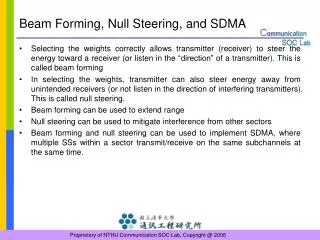
!!! Common Regions !!! • While threading one beam, one has to pay attention to COD in the common regions, since exciting them will also affect the beam that comes later. The algorithm(s) may pick a common region COD to correct an error that is actually located nearby in the non-common region not ideal for the other beam !! • There are various strategies to cope with the common regions: At one extreme… • Do not touch common region CODs before both beams are circulating together. • May not work…. At the other extreme… • Steer each beam without paying attention to the common regions. • When switching from one beam to the other, reset the common region CODs to zero or whatever optimum kick of the other beam. • When both beams are circulating individually: • Compute the bare orbit for each beam (unfold all kicks). • Calculate a combined correction for both beams. • Inject both beams on the newly corrected orbit, it should work… 10
First Turn to Closed Orbit • When the beam reaches the end of the first turn, either it will make N (N > 2) turns right away, or one has to work a bit more on the first turn.... • When the beam makes ‚multiple‘ turns, a closed orbit can be obtained by • Closing the second turn on the first • - a priori only a fraction of turn 2 needed (< 20%). • Estimating the CO from average of turn 1 to N, followed by CO correction • >> Both options are available • When you start working on the CO, optics errors (tune off, beta-beat) start to strike you and can make corrections diverge: • In case of convergence problems, need to check Q / optics. 11
Steering is affected by… • BPM calibration factors (and offsets) • - Isolated errors are not critical at the beginning (depends on HOW one steers). • Corrector calibrations and polarities. • Optics model uncertainties. • - Beta beating. CO steering Ok until ~50%, stops working around 100%... • - Tune error : CO response ~ 1/sin(Q) • >> divergence if Q approaches integer, or if Q far away from model. • >> The steering application provides automated response measurements to probe calibrations & optics. • Output in format suitable to inject into fit program... • Used extensively all over the SPS + LEIR. • For the LHC results may not be available immediately. The fits can be tricky due to the large number of parameters.... 12
Response Measurements : how much? The response measurement of a corrector involves applying a +kick and then a –kick and record the orbit (or trajectory) for each case. Time requirement : • ~ 20 seconds /corrector. • Possibly more if done with trajectory (SPS supercycle length defines time). Data sample sizes : • BPM calibration only : 2-4 correctors/plane/arc sufficient. • Rather fast (~< hour). • Corrector calibration: ALL ~1060 correctors in the ring • Lengthy... count 2 shifts. • Must be done sooner or later. • Optics model: similar to BPM calibration case 13
Calibrations : when? • The more parameters, the heavier the fit... • >> Ideally perform systematic BPM/corrector calibration when the optics model is corrected (by other means). • If there are problems with CO correction/first turn and there is a suspicion on the optics, limited number of measurements with first turn. • Determine tune value. • Identify major error sources. • >> Successful for TI2, TI8 & CNGS – but much reduced ‘scale’. • Else • Insert into commissioning as needed/when suitable. • Corrector calibration: • At the latest just before orbit FB commissioning 14
TI2 Example : online diagnostics possible ! • One can detect optics errors ONLINE with a few clicks by comparing the model response with a measurement. And correct the machine… • Below an example for TI2 : Model Trajectory difference (response to a kick) The phase advance (tune) is wrong (by ~1%) 15
Calibration Factors • Calibration factors can be edited ‘on-the-fly’ (very useful for SIGN errors) while steering to avoid loosing a BPM. • >> BI does not have to intervene right away !! • Default calibration factors may be saved (file) and loaded at program startup. DB storage may be implemented if required….. • Editable : • Position, calibration & offset • ‘OP Enable’ : manual enable/disable 16
BPM offsets & K-modulation • The response measurements do not determine possible BPM offsets. • In case we have suspicions on BPM offsets, we have the option the perform K-modulation on some magnets. • BPM offset determination by K-modulation. One has to : • Modulate (individual quadrupole) strength: • OK for insertions (ind. powering), not for arcs. • Strength changes at the 0.1% level, sinusoid. • Bump beam back and forth in the quadrupole (steering application). • Measure orbit oscillation. • Track with BBQ system. • >> ‚Bumping‘ will be automated in the steering application. • >> Need SW for the analysis : • Correlation of orbit data in quadrupole with BBQ data. • Fit of offset. 17
Intensity Mode • When the BPM system is switched to intensity mode, the intensity data of beam X is returned as position data of beam Y. A sort of mess... • - Need special mapping of the data of one beam to the other. • - For the moment intensity would appear as position of the other beam. • The BPM trigger threshold is around 1-2x10⁹ p: • With pilot intensity the usefulness of the intensity mode is rather limited... • With pilot : not trigger gone below 1-2x10⁹ p... • To be useful the intensity mode requires more beam to be injected ! • See R. Jones’ presentation ! 18
Energy Offset Measurement & Correction • Relative energy can be easily determined arc by arc for each beam. • Dynamically generated ‘internal knobs’ are available to correct individual arcs with orbit correctors. Perturbations to rest of the machine is minimized. Example : 0.1% dp/p arc 23 Position change Corrector settings 19
Local CO Corrections • The LEP ‘short length’ correction algorithm (Limberg & Herr) is available. It was used extensively at LEP for local corrections in insertions. • Applicable only for single beam/outside the common regions !! Before correction Difference After correction 20
Local 2-beam CO Corrections • The LEP ‘short length’ correction algorithm was extended to provide a simultaneous correction of both beams in the insertions including the common regions. Solves both boundary conditions. Before correction Difference After correction Beam 1 Beam 1 21
Bumps • 3C and 4C bumps may be build at any location in a ring or a line. • The correctors may be defined automatically or manually (long bumps, tricky local optics conditions…) • Once it is calculated a bump can be scanned back and forth with simple clicks. • Automated bump scans will become available: • It is be possible to implement “simple” automatic scans to constant amplitude in mm or in sigma based on a user selection of locations. • >> Note that such scans may drive the beam into the aperture… Detailed bump shape plot (SPS example) 22
Slow Feedback • A feedback module is incorporated in the application for : • ‚Slow‘ orbit feedback : ~0.2 Hz sampling & correction @ LHC. • Not applicable when PCs are executing a ramp/table. • Only for injection plateau, top energy. • Energy correction feedback with CODs (injection). • - Can be implemented on short timescale. • - Wait to gather some experience before implementing. • First turn correction feedback with transfer line (TI2/TI8). • - Can be implemented on short timescale, see above. • - TIx lines & SPS extraction are very stable. Not needed on a shot by shot basis (tbc). • !!! Slow feedback will not work during ramp & squeeze where you need it most !!! 23
Middleware, JAVA & LSA have conquered the world ! …. a small group in remote corners of BI & OP is still resisting… They think that we need to control the beam Faster than what is provided by ‘world standards’! All the world ?? 24
LHC Orbit Feedback • The requirements on the stability of the LHC orbit imply real-time control in critical phases of the ramp and the squeeze which is not provided by LSA. • See Ralph’s presentation on collimation… • At some stage manual playing will be ‘forbidden’, or may lead to immediate quench ! • Given the number of requirements for beam stability the feedback will perform a GLOBAL stabilization (and not multiple local FBs). • The feedback stabilizes the orbit around a PREDEFINED REFERENCE. It will not ‚find‘ the golden orbit. • Although the absolute requirements @ LHC look more relaxed than for third generation light sources, LHC has unique difficulties: • Size • Optics changes in the presence of high intensity beams • Xing angles & separation bumps • Intensity variations 25
Orbit Feedback Architecture Surface Tunnel • Central collection of BPM data from in ~ 70 front-ends. • Correction via RT input of the power converters (~ 50 gateways). • Data transfer over Ethernet/UDP protocol – no CMW !! • >> Same architecture used for Q & Q’ FBs Database &OP Operating frequency 10-25 Hz CMW feedback unit BPM-Frontend PC-Gateway Ethernet UDP/IP Ethernet UDP/IP Service Unit Interface to DB & OP Data publication Matrix preparation… BPM-Frontend PC-Gateway ... ... BPM-Frontend PC-Gateway BPM-Frontend PC-Gateway Orbit Feedback Controller BPM-Frontend PC-Gateway 18 BPMs/crate 16 CODs/gateway ... ... 26
LHC beam response Full LHC Beam-Based FB Control Scheme (Skew-) Quadrupole settings ΔQ,ΔC- Σ Tune/Coupling Controller Qref,C-ref Qavg Q'ref ΔQmod Sextupole Settings Q' Chromaticity Reconstr. Σ Chromaticity Controller f0+Δf, Δp/p A∙sin(2πfe) reference signal φ Δf Phase Detector Low-pass Filter PLL-Control Law e.g. PID NCO orbit ref. δ, Δp/p, Δf Δp/p RF modulation Orbit Feedback Controller A∙sin(2πfe) Σ R(fe)∙sin(2πfe+φ) beam response Δf (12x/10x) 16x2 32x 1075x2 530x2 x2 2x2 BBQ BPMs CODs RF mini- AC dipole/ damper 2 (+2) x 2 Orbit/Energy Feedback Tune/Coupling PLL Chromaticity Tracker/Feedback Tune/Coupling Feedback LHC FBs: 2158 input devices, 1136 output devices → total: ~3300 devices!
Orbit Feedback Status • Data concentration of BPM data in FB controller operational. • - Note that only a fraction of the BPM FECs is operational. • FB controller in advanced state. • Data exchange to PC gateways tested. • - Systematic tests to be done. • Publication of concentrated data to the rest of the CERN World almost ready. • User interface for FB control to be done. Only expert control so far. • Interface to LSA (optics) in progress. • - Waiting for LSA refactoring to finish... • Advanced features (squeeze, Xing angles ...) in preparation... • >> We expect to be ready to operate the orbit FB by June • for injection & ramp, maybe more... 28
Orbit Feedback Plans >> Aim is to switch on as soon as possible... Requirements : • BPM calibrations checked. • COD calibrations and mappings checked. • Reasonable optics (beta-beat < 50%). Profit from ‘Space-time’ decoupling for commissioning : • Control in ‘space’ (steering algorithms ) must be working. • Control in ‘time’ (FB gains …) relaxed in the beginning. A stable orbit is one problem less to worry about ! 29
Conclusions • The steering application for the LHC is well advanced and tested. • More powerful than the LEP application of October 2000... • Too powerful for a safe LHC?? • Orbit FB is expected to be ready for the first beam. • The invincible gauls are prepared for the commissioning battle ! 30