Primer on Beam Steering: MICADO Algorithm and Relevant Steering Issues
680 likes | 707 Vues
Learn about steering algorithms, MICADO, SVD, trajectory perturbations, and more. Understand the effects of kicks, non-linear fields, and response to perturbations in beam steering programs. Explore the efficient MICADO algorithm for solving the steering problem.

Primer on Beam Steering: MICADO Algorithm and Relevant Steering Issues
E N D
Presentation Transcript
A Primer on Beam Steering J. Wenninger • Steering algorithms • MICADO • SVD • Bumps • And some more… • Selected features of the steering program • Special steering issues for the SPS
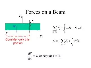
Trajectory/orbit perturbations • The trajectory or orbit of a beam is affected by DIPOLE deflections, ‘kicks’ that are represented by the symbol q. • The kick can be due to : • Field errors of the (main) bending (dipole) magnets – not all magnets have exactly the same field. • Misalignments Dx of higher multi-pole magnets : • Quadrupoles : q = K Dx • Sextupoles : q = K2Dx2 • .... • Quadrupole misalignments are the dominant perturbations at SPS and LHC. • Effects of non-linear (> quadrupole) fields can usually be neglected for steering linear optics !!! Non-linear fields only contribute at large amplitudes.
Response to kicks The position change ui at an element labeled by i due to a kick at an element labeled by j is given by : where, for the uncoupled case (H and V planes independent) : A kick only affects downstream elements ! Trajectory Closed orbit • is the betatron function, m the phase advance. Q is the tune. • Note : for Q = integer, Rij diverges for the closed orbit – INTEGER resonance!
Examples • Free oscillation : ‘cos’ term. • Modulated in amplitude by b (local optics). • ‘Kink’ at location of the kick. SPS ring H plane – kick at MDH.622 CNGS transfer line V plane, no effect upstream of the kick.. • Free oscillation starting at the kick.
Optics issues • If the optics is known, it is easy to evaluate the effect of a kick ! • The steering program uses the betatron functions, phases… stored in the DB to reconstruct the R matrix. • Global corrections (MICADO, SVD) work quite well up to beta-beat (error) of 50%, breakdown starts around 100% beta-beat. • SPS ring has a beta-beat of 10-20% - depends on optics & energy. • In general coupling is not an issue at SPS and LHC. Horizontal and vertical planes can be handled independently. Exception : • TT10 for fixed target beam where the planes are exchanged: • H plane in the PS V plane in the SPS and vice-versa (aperture optimization). • For TT10 the analytic expressions breaks down and a response matrix must be calculated numerically with MADX. • LHC in the very first days (?). But should be manageable.
The ‘steering problem’ • We have N BPMs that give us the beam position ui at their location. • We have M correctors that can provide deflections qi. • We assume that we know the response between BPMs and correctors (Rij). • Expressed in vector and matrix format : A change of the correctors by Dqj leads to a position change :
The ‘steering problem’ Given a set of measured beam positions um,i we are interested to find corrector kick changes Dqc,j such that the resulting beam position uri is minimized : By minimum I mean that the norm ( r.m.s.) is minimized : Steering consists basically in solving this LINEAR equation !
MICADO for non-mathematicians • MICADO (Minimization Carrees ….) is an algorithm developed by B. Autin and Y. Marti for the PS in the 1970’s. • MICADO solves the steering problem by an iterative search for the most effective corrector: • The jth column of the response matrix R holds the effect of a kick at the jth corrector on the beam position: Compare to… Effect of the 1rst corrector • MICADO compares the response of each corrector (column of R) with the measured position. It scans through the correctors to find the one with the closest pattern, i.e. that will lead to the largest reduction of the residual r.m.s.
MICADO iterations • Iteration 1 : find the most effective corrector. Compute its kick and the residual position. • Iteration 2 : find the most effective corrector (for the residual position) among the remaining M-1 correctors. Compute its kick and re-evaluate the kick of the first corrector. Compute the residual. • … • Iteration K : find the most effective corrector (for the residual position) among the remaining M-(k-1) correctors. Re-compute its kick and re-evaluate the kicks of the k-1 first correctors. Compute the residual position. • … • Note : • At each step all kicks are re-evaluated to find the best COMBINED solution ! • Once a corrector is selected, it is never deselected. • As a result of the kick re-evaluation, it is possible that a kick that is selected initially is set back to 0 at iteration K !
MICADO features • MICADO is very efficient to find isolated (large) kicks. • MICADO can be fooled by measurement errors (noise, offsets) : MICADO may not find the kick at the correct place, but at a phase of ±180 degrees with respect to the ‘exact’ location. • MICADO is sensitive to bad response matrix structures due to missing BPMs, bad design of the machine… To avoid numerical problem one can ‘recondition’ the matrix to detect possible candidates for numerical problems and ‘remove’ them. • Be careful when using MICADO with a very large number of correctors (for example > 20 correctors @ SPS) : • Check the strengths to avoid excessive deflections from noise, offsets…. • It is always possible to correct iteratively: • Pick a few correctors, send them. • Continue on the resulting orbit with another coupled correctors. • Etc…
MICADO in practice Checkbox defaults depend on the line/ring! Kicks before, difference & predicted kicks after. Position before, predicted difference & predicted result
MICADO iterations Corrector results in text form De-selection of iteration info - speed !! (Only significant for LHC !) Position results in 2D + projection Corrector results in 2D + projection 2D plots show the absolute values of the kicks/positions ! ‘white = zero’
More on iterations For every correction type based on iterations, a plot showing the evolution of the position and kick rms is automatically produced !
SVD • The acronym ‘SVD’ stands for ‘Singular Value Decomposition’. • It is an algorithm to invert non-square or singular matrices. • In the context of beam steering, the interest of SVD can be explained by some of the properties of this decomposition – it is widely used in all modern (second & third generation) light sources for feedbacks. • In the presentation I will give a somewhat ‘un-conventional’ (but without big maths) explanation of the way SVD works and why it is interesting…
Coordinate systems • To describe the coordinates of a point P in space, one usually chooses a reference system (e1,e2) that is orthogonal, i.e. the angle between any pair of axis vectors is 90°. • In addition the basis vectors are usually normalized, i.e. they length is ‘1’ unit. • In this example, (e1,e2) constitutes an orthogonal and normalized base of the 2-D space. • Usually the choice of the reference system is arbitrary, or just given for practical reasons (simplicity…). • A transformation matrix can be used to move from one coordinate system to another one, i.e.: • It is also possible to choose a non-orthogonal reference system – but with the drawback that computations become (much) more difficult ! P= x1e1 + x2e2 P P x2 e’2 e2 P= x’1e1 + x’2e2 e’1 x’1 x’2 e1 x1 P x2 e2 x1 e1
Position and corrector space In the context of beam steering, we have a position and a kick space, both of very high dimension (N and M). The two spaces are coupled by the response matrix R. R Corrector Setting q2 u2 Beam Position monitor2 monitor2 corrector2 corrector2 monitor1 monitor1 corrector1 corrector1 u1 q1 The ‘heart’ of the steering problem : orthogonal directions in the corrector space are transformed into non-orthogonal direction in monitor space by R (and vice-versa…) !! This is due to the accelerator lattice that couples the responses !! The mathematical difficulty of steering is due to the fact that the individual corrector responses do not form an ORTHOGONAL basis of the monitor space ! R R
Orthogonal responses ? Question : Is it possible to find a basis of the corrector space (by mixing correctors) such that a transformation by R preserves orthogonality ? monitor2 corrector2 monitor1 corrector1 R Answer : YES it is possible – this is what SVD does for us !!! The price to pay: instead of working with single PHYSICAL correctors, one will have to work with mixtures of correctors. R
SVD • The SVD decomposition builds corrector combinations that are often referred to as ‘eigenvectors’ of R (although they are not really in the mathematical sense): with • The M solutions (as many as they are correctors) have the desired property of being orthogonal and normalized : • for the corrector space (they form a complete base of the space) • for the monitor space • The ‘eigenvalues’ or ‘weights’ wj is proportional to the r.m.s. position change obtained by applying the corresponding corrector eigenvector: The larger wj, the more efficient the eigenvector !
SVD decomposition examples Sorted eigenvalues for the SPS and LHC rings. There are as many solutions as correctors ! SPS H plane Ratio max/min ~ 100 Very regular lattice ! LHC H plane – 2 coupled rings – IR1&5 squeezed Ratio max/min ~ 10’000 ‘Near singular’ solutions in the LHC IRs ‘Singular’ solutions (i.e. very poor ratio reponse/kick strength). Can lead to problems for MICADO !
Eigenvectors examples : LHC No. 1 No. 137 As the eigenvalues decrease, the associated eigenvectors correspond to increasingly local ‘structures’ No. 516
Corrections with SVD • The position measurement is decomposed uniquely into the monitor eigenvectors. The residual is the un-correctable part of the measurement. • The coefficients cj are obtained from a very simple and very fast operation (know as ‘scalar’ product). • The same cj are used to compute the correction kicks Dq, because there is a direct correspondence between the eigenvectors vectors in position and corrector space. The correction may use between 1 and N eigenvectors (the ‘user’ choice). • Note : the number of eigenvectors controls how ‘local’ the correction will be: • Few eigenvectors corrects only global structures.
SVD more formally… • In mathematical terms, the SVD algorithm decomposes matrix R into 3 matrices Z, W, and V : with The eigenvectors described on the previous slides are stored in the columns of Z and V • The correction using k eigenvalues is given by : ‘pseudo-inverse’ of R
SVD • Computing speed: • The SVD decomposition is CPU intensive, Time ~ (N,M)3 : • SPS ~ 200 ms, LHC, 2 rings ~ 20 s ! • The correction itself is very fast : SPS ~ 1 ms, LHC ~ 10 ms. • As long as the BPM/corrector pattern is constant, decomposition must not be redone. • SVD corrections go from global (few eigenvectors) to local correction (many eigenvectors). • Not suited to identify few isolated kicks. • Can be used to correct few large kicks with a large number of small kicks. • Can be configured to be insensitive to bad BPMs (limit to largest eigenvectors). • The kick strengths used by SVD tends to increase monotonically as the number of eigenvectors is increased: • SVD is useful when the corrector strength is limited. Example :SPS at 400/450 GeV. • SVD is well suited for real-time feedbacks: • Requires less corrector strength. • Stable and fast computing time (correction only!). A MICADO correction with all correctors or an SVD correction with all eigenvectors yield the same result !
Test case 1 : MICADO An easy one for MICADO : the kick is located at the first iteration Kick convergence Orbit convergence
Test case 1 : SVD • As this is a single isolated kick, a large number of eigenvectors (~ 100) are required to find the single kick. • With 20 eigenvectors, the correction is ‘reasonable’ Kick convergence Orbit convergence
Test case 2 : MICADO • With the SPS lattice MICADO jumps on the two correctors around the monitor and builds a bump around the bad reading. Kick convergence Orbit convergence
Test case 2 : SVD • SVD is much less sensitive to the isolated BPM error and it takes a large number of eigenvectors (~ 100) to build the same bump than MICADO. • With 20 eigenvectors the perturbations are not ‘very’ large. Kick convergence Orbit convergence
Local bumps /1 • Simple bump algorithms can be used to steer the beam at one location. • The simplest bump is the 2-corrector bump: Target • Controls only the amplitude. Angle at target depends on local optics. • Requires perfect positioning of C2. • Ad-hoc conditions for 2C bump are almost never encountered. C2 C1 • The 3-corrector bump is a robust and universal bump: Target • Controls only the amplitude. Angle at target depends on local optics. • Closure with C2 & C3. • This bumps works almost anywhere, except for rare phase conditions between the correctors. C1 C2 C3
Local bumps /2 • The 4-corrector bump gives full control over position and angle: Target • Controls amplitude and angle. • Closure with C3 & C4. • This bumps works almost anywhere, except for rare phase conditions between the correctors. C1 C3 C4 C2 A trivial ‘extension’ is the ‘½’ 4-corrector bump that is used for orthogonal steering (angle & position) at targets & splitters, for first turn corrections.. : Target C1 C2
Local bumps in practice • The steering program allows you to build 3C and 4C bumps at any location in any ring or line. • But due to the local optics, ‘good’ bumps cannot be build everywhere (missing correctors, strange phase advance…) : always check the bump shape and strengths. • SPS ring: 3C bumps work much better than 4C bumps due to the 90 phase advance per cell. • TT10 with FT beams : due to the coupled optics the algorithms break down in the skew section. • … • By default the correctors for the bump are identified automatically. • You can select the correctors manually: for difficult regions (optics) or to make more sophisticated bumps (long bumps…) Select a BPM from the DV as target for the bump. Select any element of the optics as target for a bump.
Bump details • A detailed plot of a calculated bump is available from the menu bar: • Location of target. • Correctors. • All elements in optics within bump range.
Local corrections • Suppose someone would like to correct the position in a region which is • larger than a single point not a bump, • smaller than the entire ring/line. • If one uses MICADO/SVD just inside the region of interest, the correction will leak out into the rest of the ring/line, because there are no boundary conditions: Leakage Leakage Region of interest For such a scheme to work, it is necessary to ‘kill’ the leakage by matching the boundary conditions.
(LEP) Short Length correction The ‘Short Length’correction developed for LEP by T.Limberg/W. Herr solves the problem using a neat idea: Leakage Region of interest Leakage Leakage Region of interest Leakage equivalent to Virtual kick q* at virtual phase and beta • Viewed from the outside, the leakage can be described as originating from a virtual kick q*: one could try to close the correction using 2 correctors on either side like a 3C bump ! • The Short Length correction proceeds in iteration: • Correct within region. • Evaluate q* and the 2 closure kicks (one on each side, selected automatically). • Add the effect of the closure kicks to the correction (affects the inside !!). • Back to 1. until no more improvement. • The short length is useful and works rather well in rings (LEP, LHC, SPS [seldom used..]) where it is sometimes desirable to correct/improve the orbit locally. • The short length does not always converge !
Threading • Steering in transfer lines or on the first turn of a ring (i.e. single pass) is sometimes referred to a threading. • The following options are available from Menu ‘Steering’ ‘Threaders’ (first turn/transfer lines ONLY): • Single point threading: • Move the beam at a selected monitor using a nearby and suitable upstream corrector. • Useful in difficult cases to flatten the trajectory along a line – for example TT20. • LEP-style threading (‘LEP Threader’): • MICADO correction in a selected sub-region of the ring/TL using a maximum of 2 correctors. • Well suited to thread in large machines like LEP & LHC. • This is basically a specialized application of MICADO.
And more… • The effect of a kick of arbitrary amplitude at any corrector can be computed and sent to the machine: • Test BPM response. • Thread beam… • Bare corrections can be evaluated with MICADO & SVD. When a bare correction is requested then: • In the first stage, the effect of all correctors is unfolded: this corresponds to the ‘bare’ orbit/trajectory that one would obtain by setting all correctors to zero (which can be done by SW but not always in the real machine !!). • In the second stage the bare orbit is corrected with MICADO/SVD. • The interest of the bare correction is that it is possible to reset/reseed the corrector settings (for example to clean up in case many correctors have been accumulated…).
The steering program:a selection of options • The steering application for SPS, LEIR (and LHC) is build on top of/integrated into the LSA control system. • It is an offspring of the LEP/SPS Motif/C steering application that was used from 92(?) to 2004: • Generic (configurable) core. • Machine dependent add-ons. • Lot’s of new stuff still to come… This following slides are not an introduction to the application, but a presentation of some special features that are useful to know !
Color conventions for elements • The following color convention is used for monitors and correctors: • The warning status is only used for SEMs at the SPS when the signals are either too higher (saturation, gain too high) or too low. • Elements with state HW error, OP disabled and Locked are ignored for steering ! • Locked elements are part of the configuration but are normally not activated (i.e. not used in steering algorithms) : • Interlocked bending magnets in TI2,TI8,TT41 that are only used during setting up. • Special corrector magnet doublets in TT10. • Special corrector magnet in the SPS (MDVB.517). • HW Error : HW returns an error status. • OP disabled : declared bad by OP. • Locked : ‘permanent’ OP disable status (DB).
Status control Edit status of elements by table. Edit status of elements through the DV. • Editable : • Position, calibration & offset • ‘OP Enable’ : OP status flag
Locked elements • Locked elements appear in violet in the DV and in the detail tables. • They are not used for steering (i.e. cannot be trimmed) and cannot be re-enabled using the standard selection. • Can be unlocked in menu ‘Status-Control’ ‘Status Control Tools’ ‘General Tools’. Make sure you know what you do before activating such elements ! Example of the TT10 corrector magnet doublets : 2 correctors side-by-side (ramp speed) with individual PCs. The deflections should be shared equally among both correctors (taken care automatically by the steering).
Corrector calibrations & status This program uses exclusively ANGLES for steering – no currents ! Edit status of elements by table. Watch OUT : Some correction elements have a calibration of -1 !! This is the case for BENDING magnets (as opposed to CORRECTORs) and is due to a different SIGN CONVENTION for deflections in MADX ! Don’t change such signs !
Data sets • There are presently up to 7 datasets (monitor readings + corrector settings) in memory at the same time. • The ‘active dataset’ is the dataset that is shown in the DV! • The predictions of the last corrections are also stored in separate dataset (for comparisons…). • CNGS ‘special’ – 4 additional sets: • Transfer no 1. & no 2. • Average Transfers 1 & 2. • Difference Transfer 1 & 2. • The datasets can be • loaded into the DV (as they are or as difference wrt reference). • used as reference dataset. • To come soon : • Post-mortem dataset (for selected lines/machines). • Not just the last, but the last N (5,10?) acquisitions.
Trim Incorporation In a pulsed machine like the SPS, it is not sufficient to calculate a correction for a given time in the cycle tc, but it is also necessary to define how such a change is propagated to earlier and later times: ? ? DK / DI tc • The propagation of trims inside a cycle is designated as ‘trim incorporation’ – and this does not just apply to steering… • The way trims are incorporated is normally defined in the LSA DB.
Incorporation rules • Default incorporation rules are defined for all particle transfers of the SPS. • For transfer lines the rules are simple : a flat function ! • For the SPS ring, the default DB rules can be displayed from menu ‘Trim’ ‘Incorporation & Skeleton’ : Custom rules for advanced users
Trims – how to send to HW New (and not finished) : an internal history of the trims that have been sent ! List of elements that will be trimmed (from the last calculated correction) The incorporation rule that will be used…
Trims • A correction can be send as many times as desired to the machine, and multiplied by any factor. • The trims are always ADDED to the existing functions. • There are 4 different ways to send the trims. • The trim is based on the LAST calculated correction. A. Increment functions by 100% of correction. Indicates the total increment. B. Increment functions by selected % of correction. C. Increment functions by factor x correction. D. Increment functions such that the total trim is factor x correction. Equivalent to A. – direct send to HW Direct CANCEL of last trim !
Data catalogs • The steering program provides 2 simple, file based data catalogs, that can be found in the ‘File’ menu: • A ‘Data Set Catalog’ : • Data files contain one acquisition and the associated corrector setting. • For references or temporary snapshots. • The data sets can be used to re-establish (reload) the corrector settings stored in the file and/or reference for corrections… • A ‘Settings Catalog’ : • Data files contain a snapshot of all steering element functions for a cycle. • Data files contain NO monitor acquisition. • The data files can be used to restore the functions for an entire cycle. • Note : It is also possible to roll back settings of one or more elements to an arbitrary time in the past using the ‘Trim Archive’ application of Delphine.
‘Data set’ catalog • The entries of the data set catalog may be reloaded into the DV for display, or as reference orbit (to compute differences…). • Once the data is displayed in the DV, you can reload the settings into the machine…
Reloading a data set • Any dataset that is loaded as active data set (i.e. is visible in the DV) may be reloaded into the machine. • Step 1:in menu ‘Trim’ select ‘Settings Reload’, this opens the panel shown below. Select the plane and click on ‘Prepare Settings’. The settings difference will be shown in the DV. • If you are happy with it… • Step 2:You can now handle the settings change like any other correction and send it to the machine. It will be handled like any trim, including incorporation rules… • Repeat for both planes, or do it just for one ! This allows you to reload the settings for a time that is different from the acq time…