Circuit Design- Light Emitting Diodes
Circuit Design- Light Emitting Diodes. Landstown High School Governor’s STEM & Technology Academy Introduction to Robotics. What is a Light Emitting Diode?. The phenomenon of electroluminescence was first observed in a piece of Silicon Carbide (SiC), in 1907 by Henry Joseph Round.

Circuit Design- Light Emitting Diodes
E N D
Presentation Transcript
Circuit Design-Light Emitting Diodes Landstown High School Governor’s STEM & Technology Academy Introduction to Robotics Introduction to Robotics
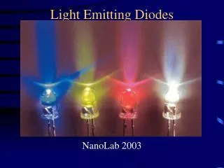
What is a Light Emitting Diode? • The phenomenon of electroluminescence was first observed in a piece of Silicon Carbide (SiC), in 1907 by Henry Joseph Round. • The yellow light emitted by it was too dim to be of practical use and difficulties in working with Silicon Carbide meant that research was abandoned. • Further experiments were carried out in Germany in the late 1920s by Bernhard Gudden and Robert Wichard Pohl, using phosphor materials made from Zinc Sulphide doped with Copper (ZnS:Cu), although once again, the low level of light produced meant that no in depth research was carried out. • In 1936 George Destriau published a report on the emission of light by Zinc Sulphide (ZnS) powders, following the application of an electric current and is widely credited with having invented the term "electroluminescence".
History of the LED • British experiments into electroluminescence, using the semiconductor Gallium Arsenide (GaAs) in the 1950s led to the first "modern" Light Emitting Diode (LED), which appeared in the early 1960s. • It is said that early experimental laboratory LEDs needed to sit in liquid nitrogen while operating and considerable effort was required to make the breakthroughs needed to create devices that would function efficiently at room temperature. • The first commercial LEDs were only able to produce invisible, infra red light, but still quickly found their way into sensing and photo-electric applications.
History of the LED • The first visible (red) light LEDs were produced in the late 1960s, using Gallium Arsenide Phosphide (GaAsP) on a GaAs substrate. • Changing to a Gallium Phosphide (GaP) substrate led to an increase in efficiency, making for brighter red LEDs and allowing the color orange to be produced.
History of the LED • By the mid 1970's Gallium Phosphide (GaP) was itself being used as the light emitter and was soon producing a pale green light. LEDs using dual GaP chips (one in red and one in green) were able to emit yellow light. • Yellow LEDs were also made in Russia using Silicon Carbide at around this time, although they were very inefficient compared to their Western counterparts, which were producing purer green light by the end of the decade.
History of the LED • The use of Gallium Aluminum Arsenide Phosphide (GaAlAsP) LEDs in the early to mid 1980s brought the first generation of superbright LEDs, first in red, then yellow and finally green. • By the early 1990's ultrabright LEDs using Indium Gallium Aluminum Phosphide (InGaAlP) to produce orange-red, orange, yellow and green light had become available.
History of the LED • The first significant blue LEDs also appeared at the start of the 1990's, once again using Silicon Carbide - a throwback to the earliest semiconductor light sources, although like their yellow Russian ancestors the light output was very dim by today's standards. • Ultrabright blue Gallium Nitride (GaN) LEDs arrived in the mid 1990s, with Indium Gallium Nitride (InGaN) LEDs producing high-intensity green and blue shortly thereafter.
History of the LED • The ultrabright blue chips became the basis of white LEDs, in which the light emitting chip is coated with fluorescent phosphors. • These phosphors absorb the blue light from the chip and then re-emit it as white light. • This same technique has been used to produce virtually any color of visible light and today there are LEDs on the market which can produce previously "exotic" colors, such as aqua and pink.
History of the LED • Scientifically minded readers may have realized by now that the history of LEDs has been a long, slow "crawl up the spectrum", starting with infra-red. • Indeed, the most recently developed LEDs emit not just pure violet, but genuine ultra-violet "black" light. • How much further up the light spectrum LEDs can "go" is a matter of speculation, but who knows ? it may one day even be possible to produce LEDs which emit X-rays.
History of the LED • However, the story of LEDs has not just been about color, but brightness too. • Like computers, LEDs are becoming roughly twice as powerful (bright) around every eighteen months. • Early LEDs were only bright enough to be used as indicators, or in the displays of early calculators and digital watches. • More recently they have been starting to appear in higher brightness applications and will continue to do so for some time to come.
History of the LED • For instance: all American traffic signals will have been replaced with LEDs by late 2005; • the automotive industry has sworn to banish all incandescent bulbs from cars by the end of the decade, replacing them with LEDs - even in headlights. • Most of the large video screens seen at outdoor events use many thousands of LEDs to produce video pictures. • Very soon, LEDs will be bright enough to light our homes, offices and even our streets as well. • The extreme energy efficiency of LEDs means that solar charged batteries can power LED units by night, bringing light to the Third World and other areas with no mains electricity.
Connecting LED’s • LEDs must be connected the correct way, • the diagram may be labeled a or + for anode and k or - for cathode (yes, it really is k, not c, for cathode!). • The cathode is the short lead and there may be a slight flat on the body of round LEDs. • LEDs can be damaged by heat when soldering, but the risk is small unless you are very slow. • No special precautions are needed for soldering most LEDs.
Defining the circuit • Ohm's Law – Current = Voltage/Resistance • One ohm is the resistance value through which one volt will maintain a current of one ampere. ( I ) Current is what flows on a wire or conductor like water flowing down a river. Current flows from points of high voltage to points of low voltage on the surface of a conductor. Current is measured in (A) amperes or amps. ( E ) Voltage is the difference in electrical potential between two points in a circuit. It's the push or pressure behind current flow through a circuit, and is measured in (V) volts. ( R ) Resistance determines how much current will flow through a component. Resistors are used to control voltage and current levels. A very high resistance allows a small amount of current to flow. A very low resistance allows a large amount of current to flow. Resistance is measured in ohms.
Forward Voltage • Diode forward voltage • If you have good specs from your supplier, you'll want to enter the typical forward voltage here. Ideally you'll have something that looks like "3.3V @ 20 mA" which defines forward voltage and current at one point on the operating curve. If you don't have good specs, here's a table to help you make decent guesses: • Forward voltage can also be remembered as the required voltage needed for the LED to light.
Forward Voltage by Color • Color voltage (Volts) • IR 1.5 • Red 2.0 • Orange 2.0 • Yellow 2.1 • Green 2.2 • true green 3.3 • Blue 3.3 • White 3.3 • UV 3.3 • blue 4.6 • Superbright 5.0
Desk Lamp Circuit • Ohm's Law – Current = Voltage/Resistance (I = E/R) Circuit specifications Current = 20 ma Forward Voltage = 3.4v DC Resistance = Voltage X Current (E*I) Answer = ? Ohm resistor
Soldering • Follow the rules and regulations covered in the teachers demonstration to solder the 180 ohm resistor to the cathode (-) lead on the LED. • Then solder the LED to the Black and Red wires on the Battery Cap. LED anode (+) connects to the Red wire and the cathode (-) connects to the Black wire. • Test your LED.