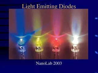
Light Emitting Diodes
Light Emitting Diodes. NanoLab 2003. Outline. Motivation/Applications: Why LED’s? Background Fabrication Testing Conclusions. Motivation/Applications: Why LED’s?. Wide range of colors Efficient and Reliable Saves money Requires less money to operate Generates less heat

Light Emitting Diodes
E N D
Presentation Transcript
Light Emitting Diodes NanoLab 2003
Outline • Motivation/Applications: Why LED’s? • Background • Fabrication • Testing • Conclusions
Motivation/Applications: Why LED’s? • Wide range of colors • Efficient and Reliable • Saves money • Requires less money to operate • Generates less heat • Good for electronics • Reduced AC costs • Last longer
Light Bulbs Filament Sudden Failure-Breaks/Burns down Recent bulbs last up to two years at ~20 lumens/watt Fluorescent tubes last about 7500 hrs at ~80 lumens/watt LED’s No filament Gradual Failure-Intensity decrease over time Last from 50,000 to 100,000 hrs (5-10 yrs) Recent LED’s (orange,red) have efficiency of ~100 lumens/watt Generate little heat Reduced A/C costs Light Bulbs vs LED’s
Applications • Communication (fiber optics) • Blue Laser Diodes • Video Recording • Data Storage • Televisions • Video Games • High Density DVD’s • DVD-ROM drive • Extra Motivation: • First company to produce efficient, reliable, cost-effective WHITE LED’s will make lots of money.
Diamond lattice Isolated Atoms > Crystal > Artificial Atom isolated atom
Background-Band Gaps and Lattice Constants • Lattice mismatch reduces efficiency
Background-Band Gaps and Lattice Constants Bandgap energy vs lattice constant of various III-semiconductors at room temperature.
Background-Band Gaps and Lattice Constants Room-temperature bandgap energy vs lattice constant of common elemental and binary semiconductors.
Background -Lattice Mismatch • Lattice mismatch reduces efficiency Two crystals with mismatched lattice constants resultion in dislocation at or near the interface between the two semiconductors.
Carrier distribution in pn homojunctions Background: pn Junctions and Recombination • Electron from donor material recombines with hole in acceptor material. • Produces photon with energy hv equal to that of the band gap. • Smaller band gaps give infrared/red light; larger band gaps give blue/UV light
Background: pn Junctions and Recombination Heterojunction under forward bias • Electron and holes are trapped in the quantum wells. • Such spatial overlap gratly enhances the recombination rate - brightness, efficiency.
Background: Ohmic Contacts Contacts • http://nina.ecse.rpi.edu/shur/Ch3/sld043.htm Relatively little resistance
Doping Hole in lower energy band allows for easier travel for electrons Electrons forced to higher, partially filled band electron moves easier
Making our Samples • We are working with two different samples • GaAsP/GaAs • GaAs/GaAs • We dope the sample with ZnAs (p-type) using the quartz ampoule method • ZnAs and our sample are cleaned using TCE, Acetone, and Methanol • Our quartz is cleaned using 2.5% HF • Seal the ZnAs and our sample in quartz with vacuum • Bake for 15 minutes for roughly 2 mm of diffusion
Making the Samples • We use a black wax (softening point at T~140oC) and 1% Bromine in Methanol etch to make contacts
Test LED’s using curve tracer Current I (mA) • Check to see that device actually works • Find turn-on voltage • P=VI, the less power it takes to operate the device, the better Voltage V (V) Red LED at 1.5V, 16mA
The Setup SpectraPro Laser Sample Optic cable Lens
The Setup Continued Curve tracer SpectraPro Setup
One of our LED’s Current (mA) Voltage (V) Red LED, 1.5V,15mA
Testing Our Sample RedLED Testing with lasers • Use SpectraPro-150 to test wavelength, relative intensity, and spectral length of our LED
Some LED’s
Conclusions • Several samples were made • Most did not reach a turn-on voltage when applying a current using the curve tracer • One LED was in the infrared range the other red • The two LEDs that did turn on were not all that efficient.
References • Photos from Jason Rausch • E. Fred Schubert • www.lightemittingdiodes.org • Craford, M.George and Stringfellow, G.B. High Brightness Light Emitting Diodes. Academic Press, 1997. • Professor Colin J Humphreys • www.sterlinggroup.org.uk/lecture2001.htm