TMS320F28335 Real-Time Interrupts
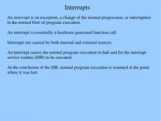
TMS320F28335 Real-Time Interrupts. What is a Real-Time Interrupt?. A Real-Time Interrupt is a segment of code that is executed at a set time interval. While this can be done using delays, we may want to have the program preforming other functions between the interrupts.

TMS320F28335 Real-Time Interrupts
E N D
Presentation Transcript
What is a Real-Time Interrupt? A Real-Time Interrupt is a segment of code that is executed at a set time interval. While this can be done using delays, we may want to have the program preforming other functions between the interrupts. A simple application for a Real-Time Interrupt is creating a blinking LED with a set period
Important Registers We will be using CPU Timer1 for the RTI • TIMER1TCR (0x0C0C) - Control Register • TIMER1PRD (0x0C0A) - Period Register • TIMER1PRDH (0x0C0B) - Period Register High • TIMER1TPR (0x0C0E) - Prescale Register • TIMER1TPRH (0x0C0F) - Prescale Register High • TIMER1TIM (0x0C08) - Counter Register • TIMER1TIMH (0x0C09) - Counter Register High
Timer Control Register Bit 15 (TIF) - Gets set on a Timer Interrupt, a write of '1' clears this flag. Bit 14 (TIE) - '1' Enables the Timer and will set TIF when Timer decrements to zero Bit 5 (TRB) - Writing a '1' will reload the the timer (Prescale and Period) Bit 4 (TSS) - Write '0' to start Timer (reset value), write a '1' to stop the Timer. A read will return the state of the clock: 0 = running, 1 = stopped. This bit is very useful for the lab!!
Loading ISR Vector When an Interrupt is triggered, several registers will be pushed to the stack and the program counter will be set to the value stored in the Interrupt Vector (see pg 83 of SPRU430.pdf) We need to set VMAP to '0' so these vectors are in the beginning of the memory map Since Timer1 is connected to INT13 we will need to load 0x001A with the memory location of the ISR (LITTLE ENDIAN FORMAT!)
Global Interrupt Initialization Since Timer1 is connected to INT13 we need to enable it in the IER. This must be done with an OR operation, NOT A MOV OR TSET! Finally, turn on Global Interrupts by clearing the INTM bit using the CLRC command
Interrupt Service Routine This is the meat of the Interrupt it will tell the program what to do when an interrupt is triggered. Two things MUST be done: Bit15 must be SET in order to CLEAR the interrupt flag. we must return from the interrupt with the IER command Finally, you want to put code in the ISR to make it do whatever is needed. (Toggle the LED in this case.)
Documentation References SPRU430, Chapter 3 contains general information on Interrupts (interrupt vector map, auto push/popped registers [important], etc.) SPRUFB0C, Chapter 3.5 contains specific information on timer interrupts, registers descriptions, and block diagrams SPRS439E, Chapter 4.2 Overview of above document