Download
1 / 67
690 likes | 925 Vues
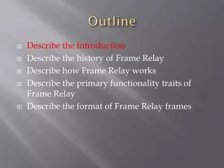
Frame Relay & ATM. Lecture 7 Paul Flynn. Virtual Circuit Switching. Digital Line Connection Identifier (DLCI). Three Phases. Data Transfer Phase. Setup Phase. Teardown Phase. Virtual circuit wide area network. Frame Relay operates only at the physical and data link layers.

E N D
Frame Relay & ATM Lecture 7 Paul Flynn
Virtual Circuit Switching Digital Line Connection Identifier (DLCI) Three Phases Data Transfer Phase Setup Phase Teardown Phase
Virtual circuit wide area network Frame Relay operates only at the physical and data link layers. Frame Relay does not provide flow or error control; they must be provided by the upper-layer protocols.
DLCI(Data-link Connection Identifier) A 'localidentifier' between the DTE and the DCE, it identifies the logical connection that is multiplexed into the physical channel. Value that specifies a PVC in a Frame Relay network. In the basic Frame Relay specification, DLCIs are 'locally significant'. In the LMI extended specification, DLCIs are 'globally significant' (DLCIs specify individual end devices). The FR Switchmaps the DLCIs between each pair of routers to create a PVC. DLCI values are typically assignedby the Frame Relay serviceprovider
Frame Relay Interface types • UNI: User-|Network Interface • NNI: Network-Network Interface NNI UNI NNI UNI PVC segment Frame Relay network Frame Relay network Frame Relay network user user Multi-network PVC
Frame RelayLocal addressing • DLCI (Data Link Connection Identifier) - identification of a virtual circuit • DLCI - of local (for a given port) meaning • there can be max. 976 VCs on an interface user-network • DLCI values: 0 - LMI channel, 1-15 - reserved, 16-991 - available for VCs, 992-1007 - layer 2 management of FR service, 1008-1022 - reserved, 1023 - in channel layer management A C To A: DLCI 121 To B: DLCI 243 To A: DLCI 182 To C: DLCI 121 B
Local Significance of DLCIs The data-link connection identifier (DLCI) is stored in the Address field of every frame transmitted.
Frame Relay Architecture Frame Relay Layers FRAD VOFR LMI
Frame Relay network VCIs in Frame Relay are called DLCIs.
Frame RelayGlobal addressing • Extension proposed by “Group of Four” • Each end user access device FRAD is assigned a unique DLCI number - a global addressTransmission to a given user goes over VC identified by a unique DLCI • Current DLCI format limits number of devices to less than 1000 • Another addition to the standard - extended DLCI addresses
LAPF Frame – Address Field 6-bits 4-bits
Frame RelayFlow and congestion control • There is no explicit flow control in FR; the network informs a user about congestion • Congestion: FR frames are discarded from overflowed buffers of switching devices • Congestion information: • FECN - Forward Explicit Congestion Notification • BECN - Backward Explicit Congestion Notification • There are recommendations for access devices what to do with FECN and BECN (usually not implemented) Transmission direction FRAD FRAD BECN FECN
Frame Relay Concepts Queue
FECN-tells receiving DTE device to implement congestion avoidance procedures FECN BECN FRAMES DLCI-identifies logical connections on the Frame Relay switch to which the customer is attached BECN-tells sending DTE device to reduce the rate of sending data.
Frame RelayParameters of a UNI interface • Physical speed - just clock rate • Guaranteed bandwidth parameters • CIR: Committed Information Rate • BC: Committed Burst Size • Extended bandwidth parameters • EIR: Extended Information Rate • BE: Extended Burst Size • TC: Measurement Interval 192kbps User traffic EIR 256kbps CIR 64kbps time
Frame RelayCIR and EIR - how does it work • BC = TC * CIR • BE = TC * EIR Bits Clock rate BC+BE CIR + EIR BC CIR Time T0 Frame 2 Frame 3 Frame 4 Frame 5 Frame 1 T0+TC Within CIR Marked DE Within CIR Marked DE Discarded
Glossary CIR (Committed Information Rate - The rate at which a Frame Relay network agrees to transfer information under normal conditions, averaged over a minimum increment of time. CIR, measured in bits per second, is one of the key negotiated tariff metrics. Local access rate - The clock speed (port speed) of the connection (local loop) to the Frame Relay cloud. It is the rate at which data travels into or out of the network. Committed Burst (Bc) - The maximum number of bits that the switch agrees to transfer during any Committed Rate Measurement Interval (Tc). Excess Burst - The maximum number of uncommitted bits that the Frame Relay switch will attempt to transfer beyond the CIR. Excess Burst is dependent on the service offerings available by your vendor, but is typically limited to the port speed of the local access loop.
More Terms ECN (Forward explicit congestion notification) - When a Frame Relay switch recognizes congestion in the network, it sends an FECN packet to the destination device indicating that congestion has occurred. BECN (Backward explicit congestion notification) - When a Frame Relay switch recognizes congestion in the network, it sends a BECN packet to the source router instructing the router to reduce the rate at which it is sending packets. DE (Discard Eligibility indicator) - When the router detects network congestion, the FR switch will drop packets with the DE bit set first. The DE bit is set on the oversubscribed traffic; that is, the traffic that was received after the CIR was met.
Data Link Control Identifier • The 10-bit DLCI associates the frame with its virtual circuit • It is of local significance only - a frame will not generally be delivered with the same DLCI with which it started • Some DLCI’s are reserved
Frame Relay Local Management Interface - LMI • LMI - a signaling protocol used on an interface: end user - network (UNI) • Implementation optional (everybody implements it...) • Usage: • notification about: creation, deletion, existence of PVCs on a given port • notification about status and availability of PVCs • periodic checks of integrity of physical connection • Planned extensions: • dynamic (SVC) channel creation and deletion • congestion notification • Also planned: LMI for network-network interface (NNI)
LMI(Local Management Interface) A signallingstandard between the CPE device and the FR Switch that is responsible for managing the connection and maintaining"status" between the devices. Set of enhancements to the basic Frame Relay specification. LMI includes support for: • 'keepalive mechanism', which verifies that data is flowing; • 'multicast mechanism', which provides the network server with its local DLCI and the multicast DLCI; • ‘globaladdressing', which gives DLCIs global rather than local significance in Frame Relay networks; • 'status mechanism', which provides an on-going status report on the DLCIs known to the FR Switch.
LMI The main purpose for the LMI process is: (management of the connection) • PVC status - What is the operational status of the various PVCs that the router knows about? • Transmission of 'keepalive' packets - Insure that the PVC stays up and does not shut down due to inactivity. Three types of LMIs are supported: • cisco - LMI type defined jointly by Cisco, StrataCom, Northern Telecom, and DEC (frame relay forum) • ansi - Annex D defined by ANSI standard T1.617 • q933a - ITU-T Q.933 Annex A LMI encapsulation types: • IETF Encapsulation Type • Cisco Encapsulation Type
Local Management Interface (LMI) • Three types of LMIs are supported by Cisco routers: Cisco — The original LMI extensions Ansi — Corresponding to the ANSI standard T1.617 Annex D q933a — Corresponding to the ITU standard Q933 Annex A
Frame Relay Map • The term map means to “map” or bind a Layer 2 address to a Layer 3 address. • An ARP table maps MACs to IPs in a LAN • In ISDN, we use the dailer-map command to map SPIDs to IP addresses • In Frame Relay, we need to map the data link layer’s DLCI to the IP address • We use the frame-relay map command
Frame Relay Map • The Frame Relay switch builds a table of incoming/outgoing ports and DLCIs. • The router builds a Frame Relay Map through Inverse ARP requests of the switch during the LMI exchange process. • The Frame Relay Map is used by the router for next-hop address resolution.
Frame RelayIARP • FRADs know DLCIs of available PVCs (through LMI), but don’t know IP addresses of other ends • IP addresses for given DLCIs are obtained automatically; mapping IP-DLCI is generated - dynamic mapping • IARP can be switched of; static maps have to be generated by FRAD user
Reachability Issues with Routing Updates in NBMA By default, a Frame Relay network provides nonbroadcast multiaccess (NBMA) connectivity between remote sites. An NBMA environment is treated like other multiaccess media environments, where all the routers are on the same subnet.
Verifying Frame Relay • The show interfaces command displays information regarding the encapsulation and Layer 1 and Layer 2 status. It also displays information about the following: The LMI type The LMI DLCI The Frame Relay data terminal equipment/data circuit-terminating equipment (DTE/DCE) type
The show interface Command LMI Status LMI DLCI LMI Type
Troubleshooting Frame RelayThe debug frame-relay lmi Command PVC Status 0x2 – Active 0x0 – Inactive 0x4 – Deleted
ATM Design Goals Problems Architecture Switching Layers
Multiplexing using different frame sizes A cell network uses the cell as the basic unit of data exchange. A cell is defined as a small, fixed-sized block of information.