Download
1 / 18
180 likes | 265 Vues
This document presents suggested enhancements to the SUN FPP proposal, focusing on OFDM numerology, modulation, coding set values, and dual-carrier modulation. Proposed changes aim to simplify design, improve robustness, and enhance system performance.

E N D
Project: IEEE P802.15 Working Group for Wireless Personal Area Networks (WPANs) Submission Title: [Suggested Improvements to SUN FPP Proposal] Date Submitted: [September 2009] Source: [T. Schmidl, A. Batra, S. Hosur, K. Le] Company [Texas Instruments] Address [12500 TI Blvd, Dallas, TX 75243 USA] Voice:[+1 214-480-4460], FAX: [+1 972-761-6966], E-Mail:[schmidl@ti.com] Re: [In response to SUN FPP proposal] Abstract: [This presentation describes several suggested improvements to the SUN FPP proposal] Purpose: [For information] Notice: This document has been prepared to assist the IEEE P802.15. It is offered as a basis for discussion and is not binding on the contributing individual(s) or organization(s). The material in this document is subject to change in form and content after further study. The contributor(s) reserve(s) the right to add, amend or withdraw material contained herein. Release: The contributor acknowledges and accepts that this contribution becomes the property of IEEE and may be made publicly available by P802.15. Tim Schmidl, Texas Instruments Inc.
Suggested Improvements to SUN FPP Proposal Tim Schmidl, Texas Instruments Inc.
Problems with Current Numerology • In the current proposal, a few of the modes result in a non-integer number of data bits per OFDM symbol • Examples: • NDSC = 100, BPSK, R = 1/2, Spreading = 4 NDBPS = 12.5 • NDSC = 22, BPSK, R = 1/2, Spreading = 2 NDBPS = 5.5 • NDSC = 22, BPSK, R = 3/4, Spreading = 1 NDBPS = 16.5 where NDSC = number of data sub-carriers and NDBPS = number of data bits per symbol • Having to support a non-integer number of data bits per symbol is awkward and leads to a more complicated design and different data path for these modes Tim Schmidl, Texas Instruments Inc.
Proposed OFDM Numerology • Supported NDSC should be 96, 48, 24, 12, and 4 guarantees an integer number of data bits per symbol and common data rates across all FFT sizes NCBPS = number of coded bits per symbol, NDBPS = number of data bits per symbol, Rate is in kbps, SNR measured at PER = 10%, 1000 bytes MCS table was modified to achieve ~3dB step size in SNR Tim Schmidl, Texas Instruments Inc.
Proposed Modulation, Coding Set (MCS) Values • By slightly modifying the MCS values, we can add more robustness to the system and ensure roughly uniform step sizes in required SNR values for a fixed packet error rate • MCS table was modified to achieve ~3 dB step sizes in SNR Tim Schmidl, Texas Instruments Inc.
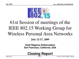
X0 X1 X2 X3 X4 X5 Source Data Encoded Data Bit Stolen Data sent/received Bit Inserted Data Decoded Data A0 A1 A2 A3 A4 A5 B0 B1 B2 B3 B4 B5 Stolen Bit A0 B0 A1 B2 A3 B3 A4 B5 A0 A1 A2 A3 A4 A5 B0 B1 B2 B3 B4 B5 Inserted Dummy Bit y0 y1 y2 y3 y4 y5 Puncturing Patterns • Define correct puncturing pattern for R = 3/4 (specification shows a puncturing pattern for R = 3/4, but it is actually for R = 2/3) Punctured Coding (r = ¾) Tim Schmidl, Texas Instruments Inc.
Dual-Carrier Modulation • QPSK: 2 bits mapped to symbol, then on to IFFT tone • MCS 4-6: there is no spreading – system has to rely solely on FEC • As the code strength decreases, start to experience diversity loss • DCM (Dual-carrier modulation): info from two QPSK symbols (4 bits) are spread onto 2 tones separated by half of signal BW • A new form of spreading which has been shown to provide a gain in frequency diversity over QPSK • Probability that there is a deep fade on both tones is quite small • Even if there is a deep fade on one of the two tones, the 4 bits of information can be recovered using a simple joint MAP decoder Tim Schmidl, Texas Instruments Inc.
Frequency Domain Spreading • SUN is expected to generally operate in low Doppler spread environments, so time diversity will be limited better to exploit the frequency diversity offered by frequency selective channels • Frequency domain spreading of 2 can be obtained by generating data symbols for the negative frequencies and copying the complex conjugates to the positive frequencies. • Frequency domain spreading of 4 can be obtained by generating data symbols for the left half of the negative frequencies. The entire block can be copied to the right half of the negative frequencies, and then complex conjugates can be used for the positive frequencies. Tim Schmidl, Texas Instruments Inc.
STF Structure • Because of the low SNR requirements, two repetitions of STF may not be enough. We propose to have 4 repetitions to ensure packets can be detected in the presence of low SNR: • To improve boundary detection performance, we propose to negate the last repetition of the last STF (“-s”) Tim Schmidl, Texas Instruments Inc.
Repetition Period for STF • Cyclic prefix is always set to 1/4 OFDM symbol, so multipath less than 1/4 symbol is fully contained within the cyclic prefix • If repetition period for STF is shorter than the length of cyclic prefix, then long channels will degrade the detection of the STF and multipath protection is determined by repetition length of the STF rather than cyclic prefix. • Propose to set repetition length of STF ≥ length of cyclic prefix Tim Schmidl, Texas Instruments Inc.
Design of STF and LTF Sequences (1) • The lowest MCS levels produce real IFFT outputs, so the transmitter for these MCSs can be simplified (e.g. only 1 DAC is needed). • If we design the STF and LTF to be real sequences in the time domain (complex conjugate symmetry in the frequency domain), then the power used in the transmitter can scale with the data rate (lower real MCS’s use 1 DAC, while higher MCS’s use 2 DAC’s) • Real sequences tend to have higher peak to average power ratios than complex sequences, so the sequences should be designed to have low PAR Tim Schmidl, Texas Instruments Inc.
Design of STF and LTF Sequences (2) PAR (dB) for STF PAR (dB) for LTF Tim Schmidl, Texas Instruments Inc.
Design of STF and LTF Sequences (3) STF Sequences STF_freq(Option-1) = sqrt(104/24)*[0,zeros(1,3),j,zeros(1,3),-j,zeros(1,3),-j,zeros(1,3),j,zeros(1,3),j,zeros(1,3),-j ,zeros(1,3),j,zeros(1,3),-j,zeros(1,3),j,zeros(1,3),j,zeros(1,3),j,zeros(1,3),j,zeros(1,31),-j,zeros(1,3),-j,zeros(1,3),-j,zeros(1,3),-j ,zeros(1,3),j,zeros(1,3),-j,zeros(1,3),j,zeros(1,3),-j,zeros(1,3),-j,zeros(1,3),j,zeros(1,3),j,zeros(1,3),-j,zeros(1,3)] STF_freq(Option-2) = sqrt(52/12)*[0,zeros(1,3),-1,zeros(1,3),-j,zeros(1,3),1,zeros(1,3),j,zeros(1,3),1,zeros(1,3),-j ,zeros(1,15),j,zeros(1,3),1,zeros(1,3),-j ,zeros(1,3),1,zeros(1,3),j,zeros(1,3),-1,zeros(1,3)] STF_freq(Option-3) = sqrt(26/6)*[0,zeros(1,3),-j,zeros(1,3),-1,zeros(1,3),-j,zeros(1,3),0,zeros(1,3),j,zeros(1,3),-1,zeros(1,3), j,zeros(1,3)] STF_freq(Option-4) = sqrt(14/6)*[0,0,-j,0,-1,0,-j,0,0,0,j,0,-1,0,j,0] STF_freq(Option-5) = sqrt(6/2)*[0,0,-j,0,0,0,j,0] * change Option-1 multiplier to sqrt(108/24) if 100 data sub-carriers are kept. Tim Schmidl, Texas Instruments Inc.
Design of STF and LTF Sequences (4) • LTF Sequences • LTF_freq(Option-1)= [0, 1,-1,-1, 1, 1,-1,-1, 1, 1,-1, 1, 1, 1, 1,-1, 1,-1,-1,-1,-1,-1,-1, 1, 1, 1, 1, 1,-1,-1, 1,-1, 1, 1, 1,-1,-1,-1,-1, 1, 1,-1,-1,-1 • ,-1, 1,-1,-1,-1,-1, 1,-1,-1 ,zeros(1,23), -1,-1, 1,-1,-1,-1,-1, 1,-1,-1,-1,-1, 1, 1,-1,-1,-1,-1, 1, 1, 1,-1, 1,-1,-1, 1, 1, 1, 1, 1,-1,-1,-1,-1,-1,-1, 1,-1 • , 1, 1, 1, 1,-1, 1, 1,-1,-1, 1, 1,-1,-1, 1] • LTF_freq(Option-2)= [0,-1,-1,-1,-1, 1,-1, 1,-1, 1, 1,-1, 1, 1,-1,-1, 1,-1,-1,-1, 1, 1, 1,-1,-1 -1,-1, zeros(1,11),-1,-1,-1,-1, 1, 1, 1,-1,-1,-1, 1, • -1,-1, 1, 1,-1, 1, 1,-1, 1,-1, 1,-1,-1,-1,-1] • LTF_freq(Option-3)= [0,-1,-1,-1,-1,-1, 1,-1, 1, 1, 1,-1,-1, 1, zeros(1,5), 1,-1,-1, 1, 1, 1,-1, 1,-1,-1,-1,-1,-1] • LTF_freq(Option-4)= [0,-1,-1,-1,1,1,-1,1,zeros(1,1),1,-1,1,1,-1,-1,-1] • LTF_freq(Option-5)= [0,-1,-1,1, zeros(1,1),1,-1,-1] • If 100 data sub-carriers are kept then use • LTF_freq(Option-1 alternative)=[0, 1, 1,-1,-1, 1, 1,-1, 1, 1, 1,-1, 1, 1,-1, 1,-1, 1,-1,-1,-1,-1,-1, 1, 1, 1, 1,-1,-1,-1, 1,-1, 1,-1,-1, 1, 1, 1, 1,-1 • ,-1,-1, 1,-1,-1,-1, 1,-1,-1,-1,-1, 1, 1,-1, 1 ,zeros(1,19), 1,-1, 1, 1,-1,-1,-1,-1, 1,-1,-1,-1, 1,-1,-1,-1, 1, 1, 1, 1,-1,-1, 1,-1, 1,-1,-1,-1, 1, 1, 1, 1, • -1,-1,-1,-1,-1, 1,-1, 1,-1, 1, 1,-1, 1, 1, 1,-1, 1, 1,-1,-1, 1, 1] Tim Schmidl, Texas Instruments Inc.
Proposed PHY Header • Useful to have reserved bits in the PHY header to allow for evolution of the standard • Currently, there are only 7 MCS values, therefore, at most 5 bits are needed to describe RATE • Typical systems will need at most 4 retransmissions to achieve application level PER, so only need 2 bits to define scrambler seed • Proposed PHY Header structure: 36 bits Tim Schmidl, Texas Instruments Inc.
Bit Interleaver • Current draft: Options 1 and 2 use a two-stage interleaver, while Options 3 and 4 use a one-stage interleaver. • Proposal: Make implementation more consistent by using IEEE 802.11a two-stage interleaver for all options: Tim Schmidl, Texas Instruments Inc.
Harmonized Symbol Rate (1) • It would be beneficial to harmonize symbol rate with the other modulation options in TG4g, this implementation, i.e., all symbol clocks can be derived from same source • Let’s look at two very common crystals – 20 and 24 MHz (just examples) • Review of FSK symbol rates: • For FSK, 24 MHz crystal can support all data rates with integer dividers Tim Schmidl, Texas Instruments Inc.
Harmonized Symbol Rate (2) • How does 24 MHz crystal work for current OFDM sample rate? Results in non-integer dividers which complicates implementation • Better choice is to use a sample rate = 1.2 Msps for 128-point FFT mode: • Recommendation change: Df = 9.375 kHz Tsym = 133.3 ms, Tcp = 26.7 ms Tim Schmidl, Texas Instruments Inc.