Random Access Methods in Data Link Layer
Learn about ALOHA, Carrier Sense Multiple Access, and more in the context of data link layer functionality with random access methods.

Random Access Methods in Data Link Layer
E N D
Presentation Transcript
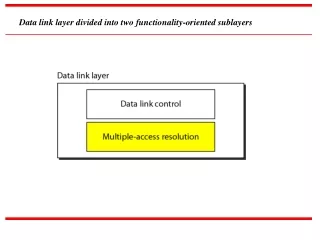
Data link layer divided into two functionality-oriented sublayers
RANDOM ACCESS In random access methods, no station is superior to another station and none is assigned the control over another. No station permits, or does not permit, another station to send. At each instance, a station that has data to send uses a procedure defined by the protocol to make a decision on whether or not to send. Topics discussed in this section: ALOHACarrier Sense Multiple Access Carrier Sense Multiple Access with Collision Detection Carrier Sense Multiple Access with Collision Avoidance
RANDOM ACCESS: Two features give this method its name. First, there is no scheduled time for a station to transmit. Transmission is random among the stations. That is why these methods are called random access. Second, no rules specify which station should send next. Stations compete with one another to access the medium. That is why these methods are also called contention methods. In a random access method, each station has the right to the medium without being controlled by any other station. However, if more than one station tries to send, there is an access conflict-collision-and the frames will be either destroyed or modified. To avoid access conflict or to resolve it when it happens, each station follows a procedure that answers the following questions: o When can the station access the medium? o What can the station do if the medium is busy? o How can the station determine the success or failure of the transmission? o What can the station do if there is an access conflict?
pure ALOHA : The original ALOHA protocol is called pure ALOHA. This is a simple, but elegant protocol. The idea is that each station sends a frame whenever it has a frame to send. However, since there is only one channel to share, there is the possibility of collision between frames from different stations. It is obvious that we need to resend the frames that have been destroyed during transmission. The pure ALOHA protocol relies on acknowledgments from the receiver. When a station sends a frame, it expects the receiver to send an acknowledgment. If the acknowledgment does not arrive after a time-out period, the station assumes that the frame (or the acknowledgment) has been destroyed and resends the frame. A collision involves two or more stations. If all these stations try to resend their frames after the time-out, the frames will collide again. Pure ALOHA dictates that when the time-out period passes, each station waits a random amount of time before resending its frame. The randomness will help avoid more collisions. We call this time the back-off time TB.
Vulnerable time for pure ALOHA protocol The vulnerable time, in which there is a possibility of collision. Pure ALOHA vulnerable time = 2 x Tfr
Note The throughput for pure ALOHA is S = G × e −2G . The maximum throughput Smax = 0.184 when G= (1/2).
Example 12.3 A pure ALOHA network transmits 200-bit frames on a shared channel of 200 kbps. What is the throughput if the system (all stations together) produces a. 1000 frames per second b. 500 frames per second c. 250 frames per second. Solution The frame transmission time is 200/200 kbps or 1 ms. a. If the system creates 1000 frames per second, this is 1 frame per millisecond. The load is 1. In this case S = G× e−2 G or S = 0.135 (13.5 percent). This means that the throughput is 1000 × 0.135 = 135 frames. Only 135 frames out of 1000 will probably survive.
Example 12.3 (continued) b. If the system creates 500 frames per second, this is (1/2) frame per millisecond. The load is (1/2). In this case S = G × e −2G or S = 0.184 (18.4 percent). This means that the throughput is 500 × 0.184 = 92 and that only 92 frames out of 500 will probably survive. Note that this is the maximum throughput case, percentagewise. c. If the system creates 250 frames per second, this is (1/4) frame per millisecond. The load is (1/4). In this case S = G × e −2G or S = 0.152 (15.2 percent). This means that the throughput is 250 × 0.152 = 38. Only 38 frames out of 250 will probably survive.
Note The throughput for slotted ALOHA is S = G × e−G . The maximum throughput Smax = 0.368 when G = 1.
Example 12.4 A slotted ALOHA network transmits 200-bit frames on a shared channel of 200 kbps. What is the throughput if the system (all stations together) produces a. 1000 frames per second b. 500 frames per second c. 250 frames per second. Solution The frame transmission time is 200/200 kbps or 1 ms. a. If the system creates 1000 frames per second, this is 1 frame per millisecond. The load is 1. In this case S = G× e−G or S = 0.368 (36.8 percent). This means that the throughput is 1000 × 0.0368 = 368 frames. Only 386 frames out of 1000 will probably survive.
Example 12.4 (continued) b. If the system creates 500 frames per second, this is (1/2) frame per millisecond. The load is (1/2). In this case S = G × e−G or S = 0.303 (30.3 percent). This means that the throughput is 500 × 0.0303 = 151. Only 151 frames out of 500 will probably survive. c. If the system creates 250 frames per second, this is (1/4) frame per millisecond. The load is (1/4). In this case S = G × e −G or S = 0.195 (19.5 percent). This means that the throughput is 250 × 0.195 = 49. Only 49 frames out of 250 will probably survive.
Behavior of three persistence methods What should a station do if the channel is busy? What should a station do if the channel is idle?
CONTROLLED ACCESS In controlled access, the stations consult one another to find which station has the right to send. A station cannot send unless it has been authorized by other stations. We discuss three popular controlled-access methods. Topics discussed in this section: ReservationPollingToken Passing
Logical ring and physical topology in token-passing access method
CHANNELIZATION Channelization is a multiple-access method in which the available bandwidth of a link is shared in time, frequency, or through code, between different stations. In this section, we discuss three channelization protocols. Topics discussed in this section: Frequency-Division Multiple Access (FDMA)Time-Division Multiple Access (TDMA) Code-Division Multiple Access (CDMA)
Note In FDMA, the available bandwidth of the common channel is divided into bands that are separated by guard bands.
Note In TDMA, the bandwidth is just one channel that is timeshared between different stations.
Note In CDMA, one channel carries all transmissions simultaneously.
Simple idea of communication with code • If we multiply each code by another , we get 0. • If we multiply each code by itself , we get 4 ( the number of station.)
Station 1 multiplies (a special kind of multiplication, as we will see) its data by its code to get d1.c1.Station 2 multiplies its data by its code to get d2 . C2.And so on. The data that go on the channel are the sum of all these terms, as shown in the box. Any station that wants to receive data from one of the other three multiplies the data on the channel by the code of the sender. For example, suppose stations 1 and 2 are talking to each other. Station 2 wants to hear what station 1 is saying. It multiplies the data on the channel by c1 the code of station 1. Because (c1 . c1) is 4, but (c2 . c1), (c3 . c1), and (c4 . c1) are all Os, station 2 divides the result by 4 to get the data from station 1.
Example 12.6 Find the chips for a network with a. Two stations b. Four stations Solution We can use the rows of W2 and W4 in Figure 12.29: a. For a two-station network, we have [+1 +1] and [+1 −1]. b. For a four-station network we have [+1 +1 +1 +1], [+1 −1 +1 −1], [+1 +1 −1 −1], and [+1 −1 −1 +1].
Example 12.8 Prove that a receiving station can get the data sent by a specific sender if it multiplies the entire data on the channel by the sender’s chip code and then divides it by the number of stations. Solution Let us prove this for the first station, using our previous four-station example. We can say that the data on the channel D = (d1 ⋅ c1 + d2 ⋅ c2 + d3 ⋅ c3 + d4 ⋅ c4). The receiver which wants to get the data sent by station 1 multiplies these data by c1.
Example 12.8 (continued) When we divide the result by N, we get d1 .