Download
1 / 60
600 likes | 940 Vues
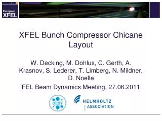
A bunch compressor design and several X-band FELs. Yipeng Sun, ARD/SLAC 2011-04-13, LCLS-II meeting. Design of two bunch compressors. Magnetic bunch compression. Bunch L phase space. 3-Dip. Chicane. e- source. RF. Dispersive region: chicane, wiggler arc, dogleg etc.

E N D
A bunch compressor designand several X-band FELs YipengSun, ARD/SLAC 2011-04-13, LCLS-II meeting
Presentation Title Page 2 Design of two bunch compressors
Magnetic bunch compression Bunch L phase space 3-Dip. Chicane e- source RF Dispersive region: chicane, wiggler arc, dogleg etc. Energy modulation (correlation): RF structure, laser, wake field etc. Bunch compression Page 3
Different bunch compressors 3(4) dipole chicane, R56 <0, T566 >0 achromatic to any order Wiggler, R56 <0, T566 >0 achromatic to any order? Arc, R56 >0, T566 >0 2-Dip. Dogleg w/ quad+sextupole, R56 >0, T566 tunable NLCTA chicane shape Chicane w/ quadrupole+sextupole, R56 tunable, T566 tunable
Dispersion relations Bunch compression Page 5
Bunch compressor with dipoles and drifts Bunch compression Page 6
General chicane (1) Bunch compression Page 7
General chicane (1) Bunch compression Page 8
General chicane (2) Bunch compression Page 9
General chicane (2) Bunch compression Page 10
An FEL with LCLS injector (S-band+X-band harmonic) Plus X-band Linac2 and Linac3 Presentation Title Page 11
Scaling 250-10pC Total length of accelerator Assume 70% RF in linac Final bunch length versus bunch charge Presentation Title Page 12
Longitudinal wake potential 'long' range Presentation Title Page 13 'short' range
Linac3 length needed for de-chirp after BC2 Presentation Title Page 14
Accelerator shape (LCLS injector + X-band) Presentation Title Page 15
LiTrack, LCLS, 250pC, 3kA Presentation Title Page 16
LiTrack, LCLS injector+X-band, 250pC, 3kA Presentation Title Page 17
Optics LCLS LCLS-Injector + X-band Presentation Title Page 18
Elegant simulation, 250 pC, 3 kA (w/ and w/o CSR) LCLS LCLS w/o CSR Presentation Title Page 19
Elegant simulation, 250 pC, 3 kA LCLS LCLS-Injector + X-band (½ R56 in BC2, 0.7 bending angle) Presentation Title Page 20
Elegant simulation, 250 pC, 5 kA LCLS (L3, 30degree) LCLS-Injector + X-band (½ R56 in BC2, 0.7 bending angle) Presentation Title Page 21
Elegant simulation, 250 pC, 5 kA, Projected emittance LCLS (L3, 30degree) LCLS-Injector + X-band (½ R56 in BC2, 0.7 bending angle) Presentation Title Page 22
Elegant simulation, 250 pC, 5 kA, Trajectory LCLS (L3, 30degree) LCLS-Injector + X-band (½ R56 in BC2, 0.7 bending angle) Presentation Title Page 23
LCLS-Injector + X-band (0.5 R56 in BC2, 0.7 bending angle), 250 pC, 5 kA Linac3 end BC2 entrance BC2 end BC1 end Presentation Title Page 24
Potential X-band advantage over S-band • Maintain a flat energy profile when pushing for shorter bunch length and higher peak current (i.e. 6kA at 250pC), due to stronger X-band longitudinal wake in Linac3, to remove energy correlation (chirp); plus possible cancellation of nonlinear chirp between RF, wake and CSR effects. • Similar or smaller CSR emittance growth in BC2, benefiting from a weaker dipole and a larger energy correlation generated in Linac2 (previous argument) • Compact (300m vs 1000m, at 14GeV) • For LCLS, increasing current from 3kA to 6kA requires a smaller L1 phase to generate a longer bunch in ~400m Linac2, so that the L wake chirp is much smaller, and the bunch is compressed more in BC2 with same L2 phase; if keeping similar L1 phase and increasing L2 phase (i.e. from 36d to 37.5), the final energy profile will be very nonlinear. Presentation Title Page 25
Elegant simulation, 250 pC, 5 kA LCLS (L1, 19degree; L2, 36degree; L3, 30degree) LCLS (L1, 22degree; L2, 37.5degree; L3, 0degree) Presentation Title Page 26
An X-band RF based FEL with optics linearization 250 pC Presentation Title Page 27
Bunch length after compression Final coordinate (square) Minimum length Minimum length Neglect small initial un-correlated energy spread 1st order optimal compression: 2nd order optimal compression: 3rd order optimal compression: Bunch compression Page 28
Full compression using optics linearization 1st order dispersion 2nd order dispersion 3rd order dispersion Bunch compression Page 29
Minimize CSR (1) short interaction time Bunch compression Page 30
New design BC1 (1) first order QF B2 0.2m 3 degree B3 0.2m -3 degree B4 0.2m -7 degree B1 0.2m 7 degree QD R56 = 17 mm
New design BC1 (2) second order SF1&2 SD1&2 symmetric K3(SF1) = -K3(SD2) K3(SF2) = -K3(SD1) T166 = T266 = 0; T566 = 170 mm
Minimize CSR (2) phase space matching X’ general X’ X’ specific CSR CSR CSR x x x Large β Small β Optimal β and α Optimized to minimize CSR impact on emittance Bunch compression Page 33
X-band based 2 stage FEL (1) 250pc, 300micron Bunch compression Page 34
Final profile at 7GeV (collimation in middle of BC1) Presentation Title Page 35
Slice emittance evolution, 250 pC, 6 kA Linac3 end BC1 end BC2 entrance BC1 entrance Presentation Title Page 36
An X-band RF based FEL with normal chicane BC 10 pC Presentation Title Page 37
Max bunch length w/o harmonic RF Bunch compression Page 38
Bunch compressor and linac design BC2 Linac cell BC1 Bunch compression Page 39
X-band based 2 stage FEL (3) 10pc, 40micron 54 MeV(C. Limborg) 6 GeV
FEL simulation Setup Juhao Wu • FEL at 2 keV , 6 Å (FEL at 8 keV, 1.5 Å) • Electron Charge 10 pC, Centroid Energy 6GeV, peak current 3 kA with profile as shown in previous slides • S2E file down to undulator entrance • LCLS Undulator with larger gap lw = 3 cm (1.5 cm); beta-function ~ 15 m
FEL performance 1.5 angstrom 6 angstrom Juhao Wu Presentation Title Page 42
BC parameters summary Bunch compression Page 43
Possible test at NLCTA Presentation Title Page 44
Motivation and simulation condition • Motivation • Demonstrate effective bunch compression (5 to 10 times) with x-band RF • Scheme 1: use normal chicane + positive RF chirp (current NLCTA) • Scheme 2: use optics w/ higher order dispersion + positive/negative RF chirp (need to install 4/6 sextupoles in the big chicane) • Investigate tolerances on timing jitter, misalignment etc.; emittance growth • Simulation condition: • In Elegant, including transverse and longitudinal wake, coherent synchrotron radiation (CSR), longitudinal space charge (LSC) and velocity bunching • 0.5 million macro-particles • For scheme 1, current operating optics • For scheme 2, new optics • 20 pC beam at 5MeV, 0.5ps RMS bunch length, 5e-3 RMS energy spread, 1 m.mrad transverse emittance • Beam energy: 60 MeV at BC1, 120 MeV at BC2 Bunch compression Page 45
NLCTA optics (current operation) R56 =-73mm T566 = 111mm R56 =-10mm T566 = 15mm Bunch compression Page 46
Scheme 1 (1) L phase, current and bunch length Initial Linac1 BC1 Linac2 BC2 Bunch compression Page 47
Scheme 1 (2) no compression, on crest Initial Linac1 BC1 Linac2 BC2 Bunch compression Page 48
Scheme 1 (3) 2 stage compress 20 times, end Bunch compression Page 49
Scheme 1 (4) effect of timing jitter, near full compression Timing jitter between laser and RF (assumed same for two RF sections) On phase + 115 fs (0.5 degree) - 115 fs Bunch compression Page 50