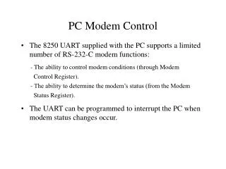
PC Modem Control
PC Modem Control. The 8250 UART supplied with the PC supports a limited number of RS-232-C modem functions: The UART can be programmed to interrupt the PC when modem status changes occur. - The ability to control modem conditions (through Modem Control Register).

PC Modem Control
E N D
Presentation Transcript
PC Modem Control • The 8250 UART supplied with the PC supports a limited number of RS-232-C modem functions: • The UART can be programmed to interrupt the PC when modem status changes occur. - The ability to control modem conditions (through Modem Control Register). - The ability to determine the modem’s status (from the Modem Status Register).
UART Port Addresses and Functions Port 1 Port 2 Address Offset Uses 0x3F8 0x2F8 Base address + 0 Transmission Register Buffer Receive Register Buffer Line Speed (LSB) 0x3F9 0x2F9 Base address + 1 Interrupt Enable Line Speed (MSB) 0x3FA 0x2FA Base address + 2 Interrupt Identification Register 0x3FB 0x2FB Base address + 3 Line Control Register 0x3FC 0x2FC Base address + 4 Modem Control Register 0x3FD 0x2FD Base address + 5 Line Status Register 0x3FE 0x2FE Base address + 6 Modem Status Register
7 6 5 4 3 2 1 0 0 0 0 DTR RTS Out1 Out2 Loop Modem Control Register • DTR: data terminal ready • RTS: request to send • Out1: not used • Out2: enable UART interrupt • Loop: enter loopback mode
MCR Example #define MCR 0x3FC #define DTR 0x01 #define RTS 0x02 #define OUT2 0x08 - To signal the modem that the PC is connected to the channel and has data to send: outportb(MCR, DTR+RTS+OUT2); - To clear the modem: outportb(MCR, OUT2);
7 6 5 4 3 2 1 0 CTS DSR RI CD CTS DSR RI CD Modem Status Register - CTS: There has been a change in the Clear to Send signal since the last time the MSR was read. - CTS: The value of the Clear to Send signal
7 6 5 4 3 2 1 0 Data available Tx holding reg. empty Receive Line Status Modem status change Modem Interrupts - UART generates 4 types of interrupts (interrupt enable register). - Modem status changes can be made to cause interrupts by setting IER to 0x08. #define IER 0x3F9 #define DATA_AV 0x01 #define TX_HR_MT 0x02 #define RVC_LS 0x04 #define MDM_CHG 0x08 outportb(IER, MDM_CHG),
7 6 5 4 3 2 1 0 Interrupt pending Interrupt id (b0) Interrupt id (b1) Modem Interrupts - Interrupt identification register indicates the cause of the interrupt. IIR Interrupt 6 Receive line status (overrun, parity error, etc.) 4 Received data available 2 TX holding Reg. empty 0 Modem status change Interrupt identification register - The status of modem can be obtained by reading the MSR status = inportb(MSR);
Example: Commkit External Modem - Extends the point-to-point utility to handle modems. - The following modem status changes are recognized: CTS, DSR, RI, RLSD (CD) - Once carrier is detected, the modem enters the DSR state and signals both DSR and RLSD to the UART. - Upon detection of DSR and DLSD, the DTE responds with DTR and RTS. - At this point, DTE is connected DCE and communications can commence.
Implementation - Three states: WAIT_FOR_CARREIR, CONNECTED, DISCONECTING - When a modem status change occurs, control is passed to low_level( ), which sends modem status to Application. - Foreground process controls the modem or sends messages to serial port via low_level( ) too. - Create two new process identifiers: MODEM_DATA --> SP1IH (send data) MODEM_CHANGE --> SP2IH (control modem) - MODEM_DATA + code=MODEMSTATUS --> AP AP --> MODEM_CHANGE both cause control to pass to modem_change( )
Implementation do_modem( ) KEYIH keyboard_data() XMITDONE MODEM_DATA (SP1IH) do_rmt_scr() MODEM_CHANGE (SP2IH)
Hayes’ Commands - Not all UART Manufacturers conform to RS-232-C signals. - Programs may not be portable across different modems. - Many modems support Hayes’ commands, a set of textual strings that are recognized and interpreted by the modem. - Hayes modem has a front-end that interprets the modem commands issued by the application software, converting them into the signals required by the modem. - When first initialized, the front-end is in “command” state, interpreting any data supplied to it. - Once a connection is established with another modem, the front-end enters the “on-line” state, passing data directly to modem.
Hayes’ Commands - +++ : from “on-line” to “command”. - AT: command prefix - DTxxxx: dial phone number xxxx. - H : hang up - O : from “command” to “on-line” - &Zn=x: assign a phone number, x, to an internal register n. - S=n: dial phone number stored in register n.
Hayes Modem State Diagram All Keystrokes To Internal Modem Command State Successful Call Out, Successful Call In, ATO Connect Message +++ OK Message On-Line State All Keystrokes To Remote
Example: Commkit Internal Modem - Internal Modem is installed as a card in PC. - Most internal modems support Hayes’ AT commands. - For a Hayes modem, - The control software is not in direct communication with UART; rather, all modem control signals are via the AT Commands. - All modem status changes are interpreted by the internal modem and returned to the control software as text via the UART’s data-available interrupt.