Modern ASIC Design with VHDL: Structured Logic Concepts
Learn modern ASIC design approach using VHDL for structured logic design concepts from high to low abstraction levels, focusing on RTL modeling, synthesis tools, and abstraction hierarchy levels.

Modern ASIC Design with VHDL: Structured Logic Concepts
E N D
Presentation Transcript
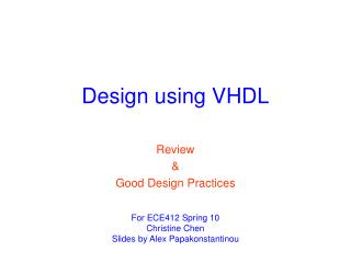
VHDLStructured Logic Design Ivan Dugic idugic@verat.net Veljko Milutinovic vm@etf.bg.ac.yu School of Electrical Engineering University of Belgrade Department of Computer Engineering
Table of contents • HDL Introduction • Structured Design Concepts • Basic Features of VHDL • Design Process Highlights Ivan Dugicidugic@verat.net
HDL Introduction Ivan Dugicidugic@verat.net
HDL Introduction Modern chip design aspects • Modern chips became too complex • The number of transistors in a modern chip is over a 100 M • Transistor count per chip and chip speed rise up to 50% per year • Estimated time needed for manual implementation (100 M transistor, 10 sec/transistor) – 135.5 years!!! Ivan Dugicidugic@verat.net
HDL Introduction Modern ASIC design approach • ASIC – Application Specific Integrated Circuit • Modeling system should be designed and described in the highest abstraction level possible • Simulation and testing at high abstraction level • Conversion of the modeled system into the low abstraction level model (gate, circuit, silicon level) using sophisticated synthesis tools • Key point – CAD (Computer Aided Design) Ivan Dugicidugic@verat.net
HDL Introduction Modern ASIC design approach • HDLs (Hardware Description Languages) are used for system description at the high abstraction level Design RTL Model Description Simulation & Testing HIGH ABSTRACTION LEVEL Conversion LOW ABSTRACTION LEVEL Gate Level Model Ivan Dugicidugic@verat.net
HDL Introduction VHDL • VHDL - VHSIC Hardware Description Language • VHSIC - Very High Speed Integrated Circuit • Development of VHDL began in 1983, sponsored by Department of defense, further developed by the IEEE and released as IEEE Standard 1076 in 1987 • Today it is De facto industry standard for hardware description languages Ivan Dugicidugic@verat.net
Structural Design Concepts Ivan Dugicidugic@verat.net
Structural Design Concepts The abstraction hierarchy • The abstraction hierarchy can be expressed in two domains: structural domain, behavioral domain • Structural domain – component model is described in terms of an interconnection of more primitive components • Behavioral domain – component model is described by defining its input/output response • VHDL is used for both structural and behavioral description • Six abstraction hierarchy levels of detail commonly used in design: silicon, circuit, gate, register, chip and system Ivan Dugicidugic@verat.net
Structural Design Concepts Design process • The design cycle consists of a series of transformations, synthesis steps: (1) Transformation from English to an algorithmic representation, natural language synthesis (2) Translation from an algorithmic representation to a data flow representation, algorithmic synthesis (3)Translation from data flow representation to a structural logic gate representation, logic synthesis (4) Translation from logic gate to layout and circuit representation, layout synthesis Ivan Dugicidugic@verat.net
Structural Design Concepts Design process • The design cycle steps can be carried out automatically in all stages except the first that is currently an active area of research • VHDL tools are used for algorithmic synthesis Ivan Dugicidugic@verat.net
Structural Design Concepts Design tools • Editors – textual (circuit level – SPICE gate, register, chip – VHDL) or graphic (used at all levels) • Simulators – stochastic (system level) or deterministic (all levels above the silicon level) • Checkers and Analyzers – employed at all levels, used for example (1) to insure that the circuit layout can be fabricated reliably (rule checkers), (2) to check for the longest path through a logic circuit or system (timing analyzers) • Synthesizers and Optimizers – improving a form of the design representation Ivan Dugicidugic@verat.net
Basic Features of VHDL Ivan Dugicidugic@verat.net
Basic Features of VHDL Design entities • In VHDL a logic circuit is represented as a design entity • A design entity consists of two different VHDL types of description: (1) Interface description (reserved word is entity) (2) One or more architectural bodies (reserved word is architecture) entity D_FF defining D FF interface (ports) D Q D FF R CLK architecture of D_FF specifying the behavior of the entity Designed digital device VHDL representation Ivan Dugicidugic@verat.net
Basic Features of VHDL Entity • The entity part provides system’s interface specification as seen from the outside and is generally comprised of: (1) Parameters (such as bus width or max clock frequency) (2) Connections (system input and output ports) entityDesignEntityNameis -- parameters … -- connections port (ports); end entityDesignEntityName; Ivan Dugicidugic@verat.net
Basic Features of VHDL Architectural bodies • Architectural bodies are specifying the behavior of the entity architectureArchitectureNameof DesignEntityNameis -- signal declarations begin -- concurrent statements end architectureArchitectureName; • There are two types of architectural bodies: algorithmic, structural • Algorithmic - at the beginning of the design process, designers usually would like to check the accuracy of the algorithm without specifying the detailed implementation • Structural - the logic design stage, detailed implementation, entity as a set of interrelated components Ivan Dugicidugic@verat.net
Basic Features of VHDL Processes • Process is another major modeling element in VHDL: ProcessLabel: ProcessName (sensitivity_list_of_signals) is begin -- sequential statements; end process; • Processes are used inside architectural bodies, specifying entity behavioral in algorithmic way • Whenever a signal in sensitivity list changes, the process is activated • Process execution is similar to program execution, barring one important difference: a process generally repeats indefinitely Ivan Dugicidugic@verat.net
Basic Features of VHDL Sequential and parallel processing • The statements within process are performed sequentially • The statements within architectural body are performed concurrent • Sequential and concurrent combination is called VHDL duality and it presents powerful mechanism for description of complex systems Ivan Dugicidugic@verat.net
Basic Features of VHDL Variables and signals • VHDL variable concept in many ways correspondents to a variable inherited from traditional sequential programming • Signals are the basic vehicle for information transmission in electronic systems • Signals model real devices’ wires and buses • Variable assignment is different from signal assignment • Main difference between variables and signals is that signal changes are visible only after process termination Ivan Dugicidugic@verat.net
Design Process Highlights Ivan Dugicidugic@verat.net
Design Process Highlights MAC (Multiply Accumulator) unit • Incoming part is based on MAC unit design and synthesis as part of Computer VLSI Systems, subject lectured by Dr. Veljko Milutinovic • Basic specification elements of MAC unit: (1) purpose – hardware support for numerous succeeding multiplication (2) Wishbone compatible (3) structural elements: FIFO, sequential multiplier, accumulator • MAC units are used as special CPU resource for digital signal processing Ivan Dugicidugic@verat.net
Design Process Highlights MAC (Multiply Accumulator) unit • MAC unit conceptual scheme: MAC unit FIFO Sequential Multiplier Accumulator Wishbone Interface data flow control data flow Ivan Dugicidugic@verat.net
Design Process Highlights MAC (Multiply Accumulator) unit • MAC unit detailed scheme – synthesis outcome: Ivan Dugicidugic@verat.net
Design Process Highlights MAC: Lessons Learned • Testing is extremely important aspect of device design • In the component design process it is essential to test all structure components of top-level entity separately, and after that top-level entity itself • While projecting MAC unit so called Regression Testing is used • Regression Testing includes testing both structural and behavioral architecture of every entity simultaneously Ivan Dugicidugic@verat.net
Design Process Highlights MAC: Lessons Learned • An example of regressive testing: entity TestBench is end entity TestBench; architecture Regression of TestBench is -- signal declaration begin BehModel: entity myModel (beh) port map (…); StructModel:entity myModel (struct) port map (…); stimulus: process is begin -- stimulation end process stimulus; Ivan Dugicidugic@verat.net
Design Process Highlights MAC: Lessons Learned verify: process (…) is begin assertbehOutSignal_i= structOutSignal_iand behOutSignal_j = structOutSignal_j report “Implementation Error!” severity error; end process verify; end architecture Regression; Ivan Dugicidugic@verat.net
Design Process Highlights MAC: Lessons Learned • Special problem in hardware component design: accommodation of VHDL source code with tool for synthesis • It is possible that VHDL code can be compiled regularly but synthesis tool registers errors • The solution of the problem: VHDL coding concerning synthesis tool requirements • It is necessary that VHDL code describes designed device as close as possible to the particular hardware elements which synthesis tool recognizes and synthesizes easily Ivan Dugicidugic@verat.net
References • James R. Armstrong, F. Gail Gray, Structured Logic Design with VHDL • Peter J. Ashenden, The Designer’s Guide to VHDL • Milutinovic Veljko, Surviving the Design of a 200 MHz RISC Microprocessor:Lessons Learned Ivan Dugicidugic@verat.net
Authors • Ivan Dugic, idugic@verat.net • Dr. Veljko Milutinovic, vm@galeb.etf.bg.ac.yu Ivan Dugicidugic@verat.net