Download
1 / 57
580 likes | 1k Vues
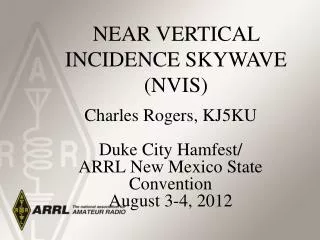
NEAR VERTICAL INCIDENCE SKYWAVE (NVIS). Charles Rogers, KJ5KU Duke City Hamfest/ ARRL New Mexico State Convention August 3-4, 2012. NVIS. Presentation Outline Definition and Applications Theory and Propagation Practical NVIS Antennas NVIS Forecast for F2 Layer

E N D
NEAR VERTICAL INCIDENCE SKYWAVE (NVIS) Charles Rogers, KJ5KUDuke City Hamfest/ARRL New Mexico StateConventionAugust 3-4, 2012
NVIS • Presentation Outline • Definition and Applications • Theory and Propagation • Practical NVIS Antennas • NVIS Forecast for F2 Layer • NVIS Antenna Designs and Builds • References and Acknowledgments
NVIS Near Vertical Incidence Skywave
Frequencies between 1.8 and 30 MHz. have three propagation modes: • -Line of sight • -Ground wave • -Sky wave • If used correctly, sky wave propagation enables us to provide continuous and dependable coverage that spans several hundred miles instead of several thousand miles. • Signal reflects off the ionosphere
Keeping in mind the limitations of MF and HF, you can do amazing things which cannot be duplicated at other frequencies. This includes Near Vertical Incidence Skywave (NVIS) Communications. • NVIS has significant importance in emergency and tactical military communications. • NVIS mode has traditionally been misunderstood and poorly appreciated
FO = Critical Frequency: The highest frequency that will not penetrate the ionosphere more than 50% of the time when radiation is directed at a takeoff angle of 90˚. HPF = Highest Probable Frequency: The highest frequency at which ionospheric propagation between specific locations will be available 10% of the time.
MUF = Maximum Usable Frequency: The highest frequency at which ionospheric propagation between specific locations will be available 50% of the time. FOT = Frequency of Optimum Traffic: The highest frequency at which ionospheric propagation between specific locations will be available 90% of the time.
LUF = Lowest Usable Frequency: The lowest frequency at which ionospheric propagation between specific locations and using specific power levels, receiving equipment and antennas will be available 50% of the time. The LUF can be improved (lowered) by increasing power, using higher gain antennas, or by substituting higher performance receiving equipment.
For NVIS to happen, frequencies must be between LUF and MUF, or you may a general rule of thumb: -Nighttime 2-4 Mhz -Daytime 4-8 Mhz The best operating frequency is usually 20 to 25% below the MUF. Propagation data is always specific to the time of year, time of day and solar activity.
NVIS propagation occurs readily at the high end of the MF range and in the lower half of the HF frequency range.
NVIS and 60 Meters • 5 “Channels” • *100 Watts PEP • Voice /*Data/ *CW • 2.8 KHz Bandwidth • Daytime Use • Ionogram shows foF2 layer height vs. freq. of approx. 5.4 Mhz
NVIS Communications occurs when the signal of an appropriate frequency is properly directed toward and reflected from the ionosphere. • This requires proper frequency selection, a suitable antenna design, and sometimes appropriate power level.
NVIS coverage has been described as being similar to the shape of an umbrella. The signal reflects off the ionosphere and emanates out at a substantial radius from the center
Takeoff angles are used to enable NVIS operation and path length. Signal strength stays fairly equal over the area of coverage.
To enable these values of takeoff angles, the antenna must be placed at an elevation that is closer to the ground. Elevation is wavelength dependent.
The type of ground has an effect on the overall gain of the antenna.
Vertical Gain of Dipole at 0.2 Wavelength Over Various Types of Ground (dBi)
The height above ground also has an effect on the impedance of the antenna; therefore, a tuner must be used. Most of the tuners that come built-in to radios are not wide enough to be used and are generally good only for an SWR of 3:1-4:1. For NVIS, we may see SWR’s as high as 200:1 or 300:1.
Remote tuners or SGC couplers may be best suited for this application. They can eliminate some of the losses incurred when coaxial cable is used.
Orientation of NVIS horizontal antenna is generally not important, since the azimuth pattern of horizontal antennas this close to the ground is somewhat circular.
NVIS Antennas and Efficiency • Higher efficiency types • Inverted V with or without reflector • Fan Dipole • Shirley Dipole • Full Wave Loop • Lower efficiency types • T2FD Various Configurations • B&W BDW-90 Folded Dipole • 90 Ft., 1.8-54 MHz Coverage, $325 • AS-2259/2268 (Collins 637K)
Fan Dipole can be used to cover multiple frequencies. Center sag can add some gain.
An inverted “V” or an inverted “V” with a reflector could be used. The inverted “V” has about the same amount of gain as a dipole as long as the included angle stays above 120˚. As the included angle gets smaller, the upward gain starts to decrease and side lobes develop.
As the included angle increases above 120 degrees, the upward gain lowers and side lobes start to develop
T2FD- B&W BDW-90 “FDMK” needed for Inverted V configuration.
T2FD- B&W Inverted “V” 3.5 MHz Center Ht. 25’ Ends 12’ 1.8 MHz Center Ht. 40’Ends 20’
Mobile NVIS Antennas • Antenna must be oriented in the horizontal position towards the back or front of vehicle • The longer the antenna the better • Consider whip antenna • Whip antenna configuration • 45 Degrees tilt • Tie down end with rope • Tilted pattern when tied towards back of vehicle • Vertical loop pattern when tied to front of vehicle
A whip tilt adapter can be fabricated to enable a mobile whip to be bent down to a more horizontal position
NVIS FORECAST for F2 LAYER “foF2”
Hourly NVIS World Map • For communications within 300 kilometers– (186 mi.) • To use the map, locate the map for your location and click on it. • The color (frequency) at your location is the optimum frequency for F2 layer NVIS communication. • Updated at 40 minutes past the hour.
Click on the maps to zoom and reload. • These maps are made from data gathered in real time around the world using HF ionospheric radar systems called ionosondes. • Mapping source: Australian Government IPS Radio and Space Services • Web: http://www.ips.gov.au/HF_Systems/6/5/
Real Time F-2 Layer • Global map of F2-layer critical frequencies. • Corresponds to the maximum radio frequency that can be reflected by the F2-region of the ionosphere at vertical incidence
Current location of the auroral ovals, the sunrise/sunset terminator and the regions of the world where the sun is 12º below the horizon which estimates the gray-line corridor where HF propagation is usually enhanced.
Used to determine the frequencies that will always be returned to the Earth. • Higher foF2 values indicate a stronger ionosphere and correspond to regions with higher MUFs. .