Switched-Capacitor Circuits
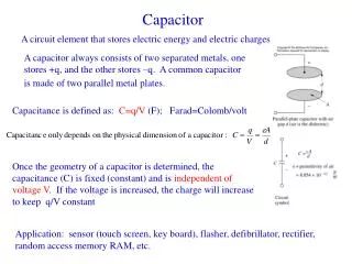
Switched-Capacitor Circuits. Continuous-Time Integrator. Approach : emulating resistors with switched capacitors. . Goal:. Concept of Switched Capacitor. A switched capacitor is a discrete-time “resistor”

Switched-Capacitor Circuits
E N D
Presentation Transcript
Continuous-Time Integrator Approach: emulating resistors with switched capacitors Goal:
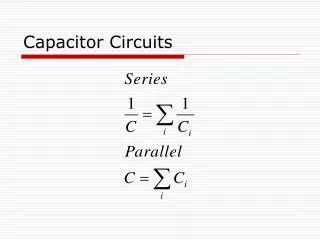
Concept of Switched Capacitor • A switched capacitor is a discrete-time “resistor” • RC time constant set by capacitor ratio C2/C1 (match considerably better than R and C) and clock period T (flexibility) Non-overlapping two-phase clock so,
Switched Capacitors Shunt-type Series-type 2-phase clock • Shunt- and series-type SCs are simple and cheap to implement • Stray-insensitive SC requires 2 more switches, what’s the advantage besides being more flexible (i.e., w/ or w/o the T/2 delay)? Stray-insensitive
Discrete-Time Integrator (DTI) What are the VTFs (z-domain) of these DTIs, assuming no parasitic capacitance is present? Shunt-type Series-type 2-phase clock
Shunt-Type DTI Charge conservation law (ideal): Total charge on C1 and C2 during Ф1→ Ф2 transition must remain unchanged! Ф1 (sample) Ф2 (update)
Shunt-Type DTI Ф1 (sample) Ф2 (update)
Series-Type DTI Ф1 (sample/update) Ф2 (reset C1) VTF:
Stray Capacitance Shunt-type Series-type • Strays derive from D/S diodes and wiring capacitance • VTF is modified due to strays • Strays at the summing node is of no significance (virtual ground)
Stray-Insensitive SC Integrator • Capacitors can be significantly sized down to save power/area • Sizes are eventually limited by kT/C noise, mismatch, etc. “Inverting” “Non-inverting” VTF: VTF:
SC Amplifier • Non-integrating, memoryless (less the delay) • Used in many applications of parametric amplification VTF:
CT Filter RLC prototype Active-RC Tow-Thomas CT biquad
SC DT Filter Active-RC Tow-Thomas CT biquad SC DT biquad
DTI + 1-bit comparator + 1-bit DAC = first-order ΣΔ ADC Sigma-Delta (ΣΔ) Modulator
SC amplifier + 2 comparators + 3-level DAC = 1.5-bit pipelined ADC Pipelined ADC
Noise of CT Integrator Noise in CT circuits can be simulated with SPICE (.noise)
Noise of SC Integrator SC circuits are NOT noise-free! Switches and op-amps introduce noise.
Sampling (Ф1) Ideal Voltage Source • Noise is indistinguishable from signal after sampling • The noise acquired by C1 will be amplified in Ф2 just like signal
Integration (Ф2) No simulator can directly simulate the aggregated output noise!
Sampling (Ф1) Noise – Cascaded Stages • Finite op-amp BW limits the noise bandwidth, resulting in less overall kT/C noise (noise filtering). • But parasitic loop delay may introduce peaking in freq. response, resulting in more integrated noise (noise peaking).
Sampled Noise Spectrum • Total integrated noise power remains constant • SNR remains constant CT DT
Nonideal Effects in SC Circuits • Capacitors (poly-poly, metal-metal, MIM, MOM, sandwich, gate cap, accumulation-mode gate cap, etc.) • PP, MIM, and MOM are linear up to 14-16 bits (nonlinear voltage coefficients negligible for most applications) • Gate caps are typically good for up to 8-10 bits • Switches (MOS transistors) • Nonzero on-resistance (voltage dependent) • (Nonlinear) stray capacitance added (Cgs, Cgd, Cgb, Cdb, Csb) • Switch-induced sampling errors (charge injection, clock feedthrough, junction leakage, drain-source leakage, and gate leakage) • Operational amplifiers • Offset • Finite-gain effects (voltage dependent) • Finite bandwidth and slew rate (measured by settling speed)
Nonzero On-Resistance • FET channel resistance (thus tracking bandwidth) depends on signal level • Usually (RonCS)-1≥ (3-5)·ω-3dB of closed-loop op-amp for settling purpose
Clock Bootstrapping • Small on-resistance leads to large switches → large parasitic caps and large clock buffers • Clock bootstrapping keeps VGS of the switch constant → constant on-resistance (body effect?) and less parasitics w/o the PMOS CMOS Bootstrapped NMOS
Simplified Clock Bootstrapper Pros • Linearity • Bandwidth Cons • Device reliability • Complexity
Switch-Induced Errors Channel charge injection and clock feedthrough (on drain side) result in charge trapped on CS after switch is turned off. • Clock feedthrough • Charge injection
Clock Feedthrough and Charge Injection • Both phenomena sensitive to Zi, CS, and clock rise/fall time • Offset, gain error, and nonlinearity introduced to the sampling • Clock feedthrough can be simulated by SPICE, but charge injection cannot be simulated with lumped transistor models
Dummy Switch • Difficult to achieve precise cancellation due to the nonlinear dependence of ΔV on Zi, CS, and clock rise/fall time • Sensitive to the phase alignment between Ф and Ф_
CMOS Switch • Very sensitive to phase alignment between Ф and Ф_ • Subject to threshold mismatch between PMOS and NMOS • Exact cancellation occurs only for one specific Vin (which one?) Same size for P and N FETs
Differential Signaling • Signal-independent errors (offset) and even-order distortions cancelled • Gain error and odd-order nonlinearities remain Balanced diff. input
Switch Performance On-resistance: Bandwidth: Charge injection: Performance FoM: Technology scaling improves switch performance!
I1 – diode leakage (existing in the old days too) I2 – sub-threshold drain-source leakage of summing-node switch I3 – gate leakage (FN tunneling) of amplifier input transistors Leakage currents are highly temperature- and process-dependent; the lower limit of clock frequency is often determined by leakage Leakage in SC Circuits Φ1 = “high”, Φ2 = “low”
Gate Leakage • Direct tunneling through the thin gate oxide • Short-channel MOSFET behaves increasingly like BJT’s • Violates the high-impedance assumption of the summing node
Switch Size Optimization • To minimize switch-induced error voltages, small transistor size, slow turn-off, low source impedance should be used. • For fast settling (high-speed design), large W/L should be used, and errors will be inevitably large as well. Guidelines • Always use minimum channel length for switches as long as leakage allows. • For a given speed, switch sizes can be optimized w/ simulation. • Be aware of the limitations of simulators (SPICE etc.) using lumped device models.
Nonideal Effects of Op-Amps • Offset • Finite-gain effects (voltage dependent) • Finite bandwidth and slew rate (measured by settling speed)
Offset Voltage Vi = 0
Autozeroing • Also eliminates low-frequency noise, e.g., 1/f noise • A.k.a. correlated double sampling (CDS)
Chopper Stabilization Ref: K. C. Hsieh, P. R. Gray, D. Senderowicz, and D. G. Messerschmitt, “A low-noise chopper-stabilized differential switched-capacitor filtering technique,” IEEE Journal of Solid-State Circuits, vol. 16, issue 6, pp. 708-715, 1981.
Chopper Stabilization Also eliminates DC offset voltage of A1
Chopper-Stabilized Differential Op-Amp • Integrators/amplifiers can be built using these op-amps • Some oversampling is useful to facilitate the implementation
Ideal SC Amplifier • Closed-loop gain is determined by the capacitor ratio by design • But this is assuming X is an ideal summing node (the op-amp is ideal)
Analog vs. Digital Supply Lines Sharing sensitive analog supplies with digital ones is a very bad idea.