Download

1 / 25
270 likes | 575 Vues
Compact RF Cavity Development at the Cockcroft Institute. Dr G. Burt Lancaster University & Cockcroft Institute. Hi-Lumi LHC crab cavity. 5 th November 2013. CI SAC Meeting 4 th – 6 th November 2013 A Wheelhouse. Crab crossing.

E N D
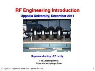
Compact RF Cavity Development at the Cockcroft Institute Dr G. Burt Lancaster University & Cockcroft Institute CI SAC meeting 29 - 31 October 2012
Hi-Lumi LHC crab cavity 5th November 2013 CI SAC Meeting 4th – 6th November 2013 A Wheelhouse
Crab crossing 4 Rod Crab cavities IR
Why do we require compact cavities? There is limited space for the crab cavities due to the opposing beamline. The cavity must within a 143 mm radius. 800 MHz elliptical 400 MHz elliptical 400 MHz elliptical Using 800 MHz RF causes a S-shaped bunch which reduces luminosity hence a 400 MHz compact cavity is desired
4R crab cavity – Cockcroft - Jlab To make suitable we increased the separation between the rods and made the rods wider. This meant they were close to the outer can.
Cavity manufacture • Lancaster and ASTeC are developing a comapct SRF crab cavity for the LHC upgrade • The structure, manufactured by Niowave was the first compact crab cavity to be tested at high field and has achieved a gradient of 3.5 MV 5th November 2013 CI SAC Meeting 4th – 6th November 2013 A Wheelhouse
First Tests The first test were performed March 2013. Cavity was not etched after bakeout hence had some surface contamination. FIRST EVER HIGH GRADIENT TEST OF A COMPACT SRF CRAB CAVITY! 5th November 2013 CI SAC Meeting 4th – 6th November 2013 A Wheelhouse
2nd Test results After a quick buffered chemical polish and ultrapure water high pressure rinse the cavity meets the design gradient.
Stainless Steel FPC We recently discovered that the couplers had accidentally been made from stainless steel instead of copper. To test the effect we simulated a cavity with no losses other than the couplers in frequency domain using the same methods as in the vertical test. Copper Q0= 7.189E9 Rs = 8.3 nOhms Stainless Steel Q0=2.737E9 Rs = 22.0 nOhms Recent tests with new couplers confirm this
Cavity welds A mistake was made in machining the rods. To fix this Niowave cut it off and welded a new one on. The magnetic field has a longitudinal component on the weld which is not ideal.
Cryomodule ASTeC have been developing a flexible cryostat for the LHC crab cavity. The cryostat has to include a beampipe for the opposing beamline and fit in the limited space within LHC. The cryostat is also side loading to allow better access during testing and commissioning A prototype cryomodule is currently being developed to allow cavity testing in the SPS. This will be the worlds first test of a crab cavity on a hadron beam. 5th November 2013 CI SAC Meeting 4th – 6th November 2013 A Wheelhouse
Prototypes The 1st CLIC crab cavity prototype has been manufactured by Shakespeare Engineering in the UK. Tolerance and surface roughness on single parts have been measured. The structure being built for high gradient test at CERN has only a single feed as it will not see beam. Structure is planned to be tested at SLAC in the near future. Cavity is being machined at VDL along with main linac structure to allow comparison of gradients.
Surface Fields Esurf Ssurf=(ExH)surf • Peak electric and magnetic fields of the dipole mode are located 90 degrees from each other on the iris • Surface Poynting flux Ssurf is however at 45 deg to both E and H • Location of the breakdown on the iris provides critical information about the role of magnetic field in breakdown. • The cavity has a large Sc but relatively low E and H fields at the surface so this also provides an independent verification of new theories. Hsurf CI-SAC Dec 2011
Cargo Screening Accelerators Aircraft ULD or pallets are too large for baggage scanners and too small for cargo scanners. Currently searched by hand. Luggage Scanning requires a few tens to hundreds keV. This can be delivered by traditional X-ray tubes up to 450 keV. Ideal energy is around 1-2 MeV but no current source available. Truck or shipping cargo is larger requires ~6 MeV. Industrial linacs can provide this.
Why X-band? • For a mobile linac mounted on a robotic arm the weight of the linac is critical. • While the linac isn’t very big or heavy the shielding is. • X-band means that the shielding diameter is much less. • Area of shielding is given by • (2rcavtshield + tshield2)p • Availability of 9.3 GHz magnetrons
1 MeV X-ray linac DC Electron Gun e2V collaboration X-ray Target Buncher and Accelerating Structure (1 MeV) CI Proposal Scope Phase-I Magnetron e2V collaboration (8-12 GHz, 1-2 MW, 100-200 Hz) Dynamic switching of amplitude and phase pulse-to-pulse) Automated Control System (Energy, rep-rate, dose) Proprietary Rapiscan Imaging and Data Analysis CI-SAC Dec 2011
Cavity Tuning Ideal profile Structure was found to have poor matching and field flatness. Low beta cells were further off frequency than could be tuned.
Linac Testing So far the linac has produced a 750 keV, 1 mA beam as measured on the spectrometer and Faraday cup/ICT. This is limited by the cavity having the incorrect e-m field pattern.
Modified structure New 490 MHz wide We have developed a new X-band structure with much greater cell-to-cell coupling to increase tolerances. Simple structure design with no slots to help tolerances (low fields and low voltage make this acceptable) Old 60 MHz wide
Cavity measurements Measurement Simulation Preliminary measurements of the new structure show good agreement with simulations.
Conclusion • The 4R Crab cavity for LHC was designed that met all specifications, unfortunately it was not selected for LHC. • CI is heavily involved in X-band structures and CLIC and are currently undertaking high gradient tests of X-band crab cavities for CLIC. • Compact Linac work is nearing commercialisation and the new structure from Comeb is performing well in low power measurements.