Clock Routing Based on X-Architecture Pattern Matching
Clock Routing Based on X-Architecture Pattern Matching. Chia-Chun Tsai Professor Dept. of Computer Science and Information Engineering Nanhua University. Dept. of Computer Science and Engineering Yuan Ze University Oct. 03, 2008. Outline. Introduction Problem Formulation

Clock Routing Based on X-Architecture Pattern Matching
E N D
Presentation Transcript
Clock Routing Based on X-Architecture Pattern Matching Chia-Chun Tsai Professor Dept. of Computer Science and Information Engineering Nanhua University Dept. of Computer Science and EngineeringYuan Ze University Oct. 03, 2008
Outline • Introduction • Problem Formulation • Proposed Algorithm • Experimental Results • Conclusion
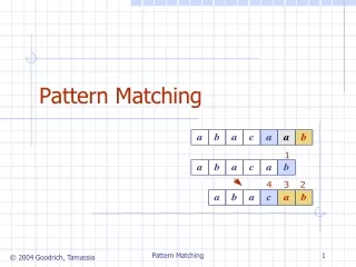
Introduction • An interesting geometric problem (Clock routing problem). • How to connect a particular point (clock source) to a number of points (clock sinks) such that each path from a particular point to the points is equal to each other. Sink Source
MMM Approach [Jackson 90] • The MMM (Method of Means and Medians ) algorithm presented with recursively partitioning. Cut 1 Cut 3 Cut 2
GMA Approach [Kahng 91] • The GMA (Geometric Matching Algorithm) based on bottom-up matching approach. H-flip
WCA Approach [Bo 91] • The WCA (Weighted Center based Algorithm) searched next tapping point withnew weighted center
DME Approach [BK92, CHH92, Eda91] • The DME (Deferred Merge Embedding):The bottom-up phase constructs a tree of merging segments and the top-down embedding phase determines the exact location. • The top-down phase in DME • The bottom-up phase in DME
GDME Approach [Wu 07] • The GDME (Grey relationanalysis forDME) for an illustration of 29 clock sinks. • Partition S by alternating x- and y-median based on MMM approach until the number of clock sinks in each partition zone, Z, is less or equal to four.
GDME Approach (Cont’d) • Use the Grey relationalanalysis and associate with the DME approach. Then, recursively split and construct a minimum-cost clock tree.
Clock Network in a Chip • A typical architecture of SoC exists a physical clock network. • Two factors for a clock network, clock delay and clock skew • Max clock delay dominates the operation frequency. • Clock skew (max clock delay – min clock delay) may fail chip functions. • Wanted: minimize the max clock delay and get exact-zero skew Clock network
Wire Delay and Sink Loading • Two typical delay models for a wire. r is a sheet resistance, ca is a unit area capacitance, cfis a unit fringing capacitance, and CL is the load capacitance of a clock sink. • The FED (Fitted Elmore delay model) (Abou-Seido 04) • Elmore delay model (Elmore 48)
Interconnection Delay • Interconnects dominate signal delay Data from ITRS Roadmap
Clock Tree Topology clock source Delay = max. delay Skew = max. delay - min. delay 20 25 level 1 7 5 7 8 level 2 2 3 3 4 4 4 4 2 level 3 Delay = 34 Skew = 34-31 = 3 31 31 32 32 34 34 33 33 Source Steiner point Sink
Manhattan vs. X-architecture Clock Routings • Manhattan routing (horizontal and vertical) • Lead to - Long wire length on average - Worse performance dominated by interconnect delay • X-architecture routing • Reduce wire length • Proviso: manufacturing technology supports diagonal routing direction. • TSMC and UMC are ready for 65-nm X-Architecture designsEE Times, May 25, 2006.http://www.eetimes.com/news/design/showArticle.jhtml?articleID=188500129 Partial routing result: Primary 1 @ 0.13m
Compared Manhattan and X- Architectures • Manhattan vs X-architecture Same area, higher performance Same performance, less area
Manhattan vs. X Architectures • X-architecture (horizontal, vertical and diagonal) • L= [(x1-x2)2+ (y1-y2)2]1/2 • LM=L(sinα +cosα) • LX=L(0.41sinα+cosα) • Benefits [Teig IWSLIP2002]: • 20% reduction in wire length • 20% saving in power • 10% improvement in chip performance • 30% reduction in die cost s2 s2 s2 Metal 4 (x2, y2) (x2, y2) (x2, y2) Metal 3 L LX LM Metal 2 α α α 45° s1 s1 s1 Metal 1 (x1, y1) (x1, y1) (x1, y1) PB X-arch. Manhattan arch. Arbitrary angle Partial routing result: Primary 1 @ 0.13m
Our Contribution • Construct ZST (Zero Skew Tree) based on X-architecture and predefined 16 matching patterns • Simplify DME merging procedures • X-flip shortens wire length • Wire sizing reduces routing resources Routing result: r1 @ 0.13m
Outline • Introduction • Problem Formulation • Proposed Algorithm • Experimental Results • Conclusion
Problem Formulation • A general CRP (clock routing problem): Given: a set of n clock sinks, S = {s1, s2, … sn} Objective: construct a ZST (Zero Skew clock Tree) based on X-architecture with better performance.
DME-4 [Shen ISCAS06] • Associated with DME (Deferred Merge Embedding) [Chao TCAD92] • Construct TOR (Tiled Octangular Region) in bottom-up phase of DME. • Resolve the exact coordinates in top-down phase of DME. • Use balanced bipartition to reduce wire length. • Delay model: FED (Fitted Elmore Delay) [Abou-SeidoTVLSI04] s1 TOR radius1 s1 s2 radius1 radius2 merging segment The construction procedure should be more easy!
Edge via Node via Metal 3 Metal 4 Metal 1 Metal 2 They use various layer definitions. Not practical enough. NVM [Wang VLSI-DAT07] • Also use DME to construct ZST (Zero Skew Tree). • Focus on NVM (Node Via Minimization). • Reducing #via is crucial. • Delay model: Elmore model
Definition of Our Clock Problem • Given: a set of clock sinks, S = {s1, s2, … sn} and a X-pattern library. • Objective: construct a ZST based on X-architecture with better performance. Preliminary • Layer definition • One bend X-pattern • 16 X- patterns as a library s2 PTN_2 PTN_1 s1
X-Pattern • Main idea: • Clock source locates near the center of routingarea. • Centralize all the routing wires. Complete routing result:r1 @ 0.13m
s2 s2 s2 PTN_2 PTN_1 PTN_1 LT RT SLT SRT SLT SRT s1 LB s1 RB SLB SRB SLB SRB PTN_1 PTN_2 PTN_2 s2 X-Pattern (cont’d) • Assumed that s1 and s2 are paired. • Step1. Tile the routing area. s1 locates in LT • Step2. Tile the routing area of s1. s2 locates in SRT • Step3. Define the X-pattern for 4 sub-zones. s2 s1 s6 s5 s8 s4 s3 s7 s2
s2 s2 s2 PTN_2 PTN_1 PTN_1 LT RT SLT SRT SLT SRT s1 LB s1 RB SLB SRB SLB SRB PTN_1 PTN_2 PTN_2 s2 X-Pattern (cont’d) s2 s1 s6 s5 s8 s4 s3 s7 s2 PTN_2 PTN_1 PTN_R PTN_R PTN_R PTN_2 PTN_R PTN_1 PTN_R PTN_1 PTN_R PTN_2 PTN_2 PTN_R PTN_1 PTN_R
Outline • Introduction • Problem Formulation • Proposed Algorithm • Experimental Results • Conclusion
Proposed Algorithm • PMXF (Pattern-Matching based on X-clock routing with X-Flip) algorithm
X14 X5 X10 X15 X8 X12 X13 X3 X11 X2 X6 X9 X4 X7 DPPG Procedure • Determine Pair of Points in GMA • GMA is a bottom-up algorithm [Kahng DAC91] • Focus on path-length balancing DPPG X1 DPPG DPPG DPPG DPPG DPPG DPPG Time complexity O(logn)
X14 X10 X8 X15 X12 X13 X3 X11 X2 SRT SLT X1 SLB SRB X6 RT LT X9 LB RB X4 CPXP Procedure • Choose Proper X-Pattern • Ex. CPXP(X1, X2) • Step1. Tile the routing area x1 locates in LT • Step2. Tile the routing area of start point, x1 x2 locates in SRT • Step3. Map the given X-pattern table CPXP(X1, X2)=PTN_1 CPXP(X2, X1)=PTN_R CPXP(X1, X2)∩CPXP(X1,X2)=PTN_1 CPXP CPXP CPXP X5 CPXP CPXP CPXP CPXP Time complexity O(logn) X7
DCTP Procedure • Determine Coordinate of Tapping Point • Tapping point, Pt is determined to achieve zero skew. [Tsay ICCAD91] • Zero skew condition ratio, x. • If 0≤x≤1, tapping point locates on wire. • If x< 0 or x>1, need snaking wire. • Use binary search to determine the coordinate. [Wu IEICE07] Time complexity O(n)
Sized wire Snaking wire Wire Sizing • Snaking wire is one of public methods for constructing ZST. • Benefits of adopting wire sizing [El-Moursy GLSVLSI03] • Release routing resources • But need extra power due to wider wires
Wire Sizing (cont’d) • Consider the zero skew condition, x < 0. Time complexity O(n)
X5 X8 X3 X2 X6 X4 X7 DME-X Procedure • Traditional DME based on X-arch. • Bottom-upphase • CreateTOR. • Merge. X1
X14 X5 X10 X15 X8 X12 X13 X3 X11 X2 X6 X9 X4 X7 DME-X (cont’d) • Traditional DME based on X-arch. • Bottom-up phase • CreateTOR. • Merge. • Top-down phase • Determinepoints’ locations. • Connect all the nodes. X1
X14 X5 X15 X8 X12 X13 X3 X2 X11 X9’ X9 X6 X4 X10 X7 DME-X (cont’d) • Our DME-X method • Integrate bottom-up and top-down phases • Construct the parallelogram • DCTP(X4, X6) • CPXP(X4, X6) ∩CPXP(X6, X4) • Tip! Run CPXP firstthen DCTP for savingrunning time. X1 DPPG Time complexity O(n)
X-Flip Procedure s2 s2 • Exchange X-pattern based on predefined patterns PTN_2 PTN_2 PTN_1 PTN_1 s1 s1 Delay = 4454.614 ps Cost = 38219.374 m Power = 0.000531 w Complete routing result:08-5 @ 0.13m
X-Flip (cont’d) • Check the length of the i-1th level when constructing the ith level. Time complexity O(n) Delay = 4139.209 ps, saving 7% Cost = 36334.753 m, saving 4.9% Power = 0.000515 w,saving 3% Complete routing result:08-5 @ 0.13m with X-Flip
Time complexityO(n) Time Complexity Analysis Time complexityO(logn) Time complexity O(n logn)
Outline • Introduction • Problem Formulation • Proposed Algorithm • Experimental Results • Conclusion
Experimental Results • Platform: WinXP-SP2 on P4-M 1.7G with 1G Memory • Compiler: Borland C++ Builder 6.0 • IBM benchmarks, r1-r5, for testing our algorithm PMXF • Our PMXF is compared with • DME-4 [Shen ISCAS06] based on fitted Elmore delay model • NVM [Wang VLSI-DAT07] based on Elmore delay model • 0.13m fabrication parameters are used.
Our Results based on FED Model • Compare our PMXF algorithm without/ with X-Flip in terms of delay, wire length, power consumption,total via, and runtime for FED model Improve 15.3% in delay Improve 3.6% in wire length and 1.3% in power Improve 0.1% in total via, but need more 12.6% in runtime
Our Results Based on ED Model • Compare our PMXF algorithm without/ with X-Flip in terms of delay, wire length, power consumption,total via, and runtime for ED model Improve 16.3% in delay Improve 4.3% in wire length and 1.5% in power Improve 0.9% in total via, but need more 10.2% in runtime
Clock Tree Construction of r5 Based on PMXF #sinks: 3101 Delay: 7.881827 ms Skew: 0 #vias: 14528 Power: 0.998684 W Runtime: 2309.672s
Our Results Compared with DME-4 • Compare our PMXF algorithm with DME-4[8] in terms of delay, wire length, and power consumption for FED model. [8] W. Shen, Y. Cai, J. Hu, X. Hong, and B. Lu, “High Performance Clock Routing in X-architecture,” IEEE International Symposium On Circuits and Systems, 2006, pp. 2081-2084.
Our Results Compared with DME-4 • The comparison of our algorithm and DME-4[8] in delay Improve 16% in delay