Download
1 / 45
450 likes | 490 Vues
Design dual-use SSTOL aircraft for efficient city-to-city travel. Compare SSTOL & VTOL costs, safety, & user preferences. Study mission requirements, response, & aircraft design. Develop tools for high-lift analysis, propulsion, costs, & more.

E N D
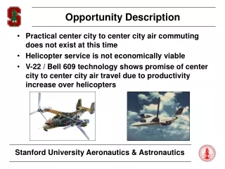
Opportunity Description • Practical center city to center city air commuting does not exist at this time • Helicopter service is not economically viable • V-22 / Bell 609 technology shows promise of center city to center city air travel due to productivity increase over helicopters
Opportunity Description (cont.) • Super Short Takeoff and Landing (SSTOL) aircraft operating from “landing” barges on rivers could provide means for practical center city to center city travel • Navy has the need for a Carrier On-board Delivery (COD) aircraft with similar payload and range - currently using the Grumman C-2 Greyhound
Project Objectives • Design a dual use SSTOL transport capable of carrying cargo and/or passengers • Compare the cost of SSTOL and Vertical Takeoff and Landing (VTOL) for the same mission • Study the inherent safety issues of one approach over the other • Assess what would be required to add a hover/vertical takeoff ability to the design • Compare the user/passenger preferences for SSTOL and VTOL
Mission Requirements • Mission Profile • Takeoff within ground roll of 300 feet (SL, SA + 27 deg F) • Cruise for 1500 nm at 350 knots • Land within a ground roll of 400 feet (SL, SA + 27 deg F) • Commercial Design Requirements • 24 passenger capacity ( ~ 4800 lbs total payload) • Military Design Requirements • Capable of carrying two (2) GE F110 engines (for F-14D) • Must meet spot factor requirement of 60 feet by 29 feet • Maximum payload of 10,000 lbs • Arresting hooks / catapult devices not allowed
‘Cardinal’ Response • Identified two most feasible approaches to meeting the design requirements: • Fixed-Wing Aircraft with USB Flaps: QSRA Boeing YC-14 • Tiltwing: Canadair CL-84 XC-142
Design Methodology • Approximately 5 month design timeline • Creating design/analysis tools for: • High Lift Analysis • Lifting Surface Design and Layout • Propulsion • Drag • Weights • Performance • Stability & Control • Cost • Design tools to be used as modules in optimization
Fixed Wing SSTOL Aircraft • Mission weight sizing using fuel fractions: • Takeoff weight: 48,600 lbs • Empty weight: 25,500 lbs • High lift system similar to that of QSRA / YC-14 • Performance sizing to meet takeoff / landing requirements: • Wing loading: 47 lb/sq ft • Thrust-to-weight ratio: 0.60 • Wing Area: 1000 sq ft • Installed thrust: 30,000 lbs
Tiltwing Aircraft • Mission weight sizing using fuel fractions: • Takeoff weight: 60,000 lbs • Empty weight: 34,600 lbs • Identified two high lift options: • Conventional Slotted Flaps • Circulation Control Wing (CCW) • Preliminary performance sizing for takeoff/landing: • Wing loading: 86 lb/sq ft • Power loading: 5.7 lb/hp • Wing area: 700 sq ft • Power: 10,500 Hp
Fuselage Layout • Fuselage overall dimensions: • Width: 13 feet • Height: 9.5 feet • Length: 60 feet
Cargo Hold / Passenger Cabin • Cargo hold dimensions dictated by size of engine shipping containers • Cargo hold length: 27 feet • More than ample room for 24 passengers in commercial version Engine Shipping Containers
Wing Layout: Fixed Wing • High wing design • Wing folding required for geometry constraints • Structure, systems, weight for folding mechanism? • Wing Geometry: • Reference Area: 1000 ft2 • Span: 47.1 ft • Aspect Ratio: 2.2 • Root Chord: 23.6 ft • Tip Chord: 18.9 ft • Mean Aerodynamic Chord: 21.3 ft • Taper Ratio: 0.8 • Code written to make all geometry calculations
Wing Layout: Tilt Wing • High wing design • Wing folding required for geometry constraints • Structure, systems, weight for folding mechanism? • Wing Geometry: • Area: 700 ft2 • Span: 49.0 ft • Aspect Ratio: 3.4 • Root Chord: 15.9 ft • Tip Chord: 12.7 ft • Mean Aerodynamic Chord: 14.3 ft • Taper Ratio: 0.8 • Code written to make all geometry calculations
Horizontal Tail Sizing • Horizontal tail sized for longitudinal stability requirements (Scissors / X-plot) • Example of horizontal tail geometry for fixed wing: • Area: 325 ft2 • Span: 29 ft • Aspect Ratio: 2.6 • Root Chord: 12.5 ft • Tip Chord: 10.0 ft • Mean Aerodynamic Chord: 11.3 ft • Code written to size tail for static margin requirement, but also need to consider tail size for takeoff rotation and trim for landing • May use lifting fan in horizontal tail for tiltwing trim
Vertical Tail Sizing • Vertical tail sized to meet One Engine Inoperative (OEI) minimum control speed requirement • Two vertical tails required to meet height restrictions • Example of vertical tail geometry for fixed wing: • Total Area: 275 ft2 • Span: 12.3 ft • Aspect Ratio: 1.1 • Root Chord: 12.4 ft • Tip Chord: 9.9 ft • Mean Aerodynamic Chord: 11.2 ft • Code written to size vertical tail for OEI control
Control Surface Sizing • Control surfaces: • Elevator • Rudder • Ailerons • Spoilers • Surfaces sized using statistical methods from Airplane Design Part II by Roskam • Trim requirements and FAR 25 / MIL-F-8785C specifications will be used to verify that control surfaces provide acceptable levels of control power
High Lift Analysis - USB Flaps • Equivalent ‘Lift Coefficient’ consists of: • Aerodynamic lift • Deflected (vectored) thrust • Increased circulation • Existing aircraft indicate a CL of 10 is achievable: • QSRA: CL of approximately 10-11 • YC-14: CL of approximately 8-9 • Difficult to analyze using ‘traditional’ analysis techniques: • superposition of lift effects found to yield CL of approximately 6-7
Rotor / Wing Interaction • Descent conversion for tilt wing aircraft often dictates sizing of rotor and wing • Significant amount of NASA windtunnel test data available • Analysis of conversion made using methodology for propeller/wing interaction in V/STOL Aerodynamics by McCormick • Results: • Calculations show significantly lower maximum allowable wing angle before separation occurs • Need to do more work !
Propulsion • Propulsion selection: • Fixed wing: Turbofan • Tiltwing: Turboprop • Preliminary engine sizes obtained from mission weight sizing and preliminary performance analysis • Fixed wing: • Thrust-to-Weight ratio (T/W): 0.60 • Installed Thrust: 29,181 lbs • Tilt wing: • Power loading (W/P): 5.7 lb/Hp • Installed power: 10,500 Hp
Engine Selection • Fixed Wing: • Geometric constraints dictate two engine configuration • Uninstalled thrust of approximately 32,100 lbs • Have data for CFM turbofan with 17,000 lbs of thrust • Tilt Wing: • Four engine configuration with two props • Uninstalled power of approximately 11,600 hp • Have data from “1989 AIAA/United Technologies Prop Data 2500 Hp Turboprop” • Needs to be scaled up
Engine Scaling Methodology • Need method to scale available engine data: Engine Scale Factor (ESF): = Net Thrust Desired/Net Thrust Base or = Net Shaft HP Desired/Net Shaft HP Base Fuel Flow Scaled = ESF 1.0 * Fuel Flow Base Corrected Air Flow Scaled = ESF 1.5 * Corrected Air Flow Base Weight Scaled = ESF 1.05 * Weight Base Length Scaled = ESF 0.4 * Length Base Diameter Scaled = ESF 0.5 * Diameter Base • Methodology not valid outside 0.80 < ESF < 1.20
Weight Estimation • Component weights calculated from equations in Airplane Design Part V by Roskam • Statistical equations based on geometry, airplane takeoff weight, ultimate load factor and design cruise speed • Weights from different methods (e.g. Torenbeek, USAF, General Dynamics) averaged • V-n Diagram • Determine ultimate load factor • Found to be gust critical - a result of low wing loading
Weight Statement: Fixed Wing • Method for estimating weight of wing folding & tilting mechanisms still to be determined (cont.)
23 ft 21ft 19ft 6.5 ft Landing Gear: Position • Main gear position = 30 ft from nose • Nose gear position = 7 ft from nose • Tipback angle, = 17 deg • Main gear lateral contact point = 7 ft from centerline • Turnover angle = 46 deg < max allowable of 63 deg
Landing Gear: Strut Loads • Takeoff weight for sample calculations = 50,000 lbs • Maximum main strut load (static) = 22,830 lbs • Maximum nose strut load (braking)= 13,100 lbs • Minimum nose strut load = 4,350 lbs • Minimum percentage of weight on nosegear = 8.7%
Landing Gear: Shocks • Main Gear • Sink speed = 15 ft/sec • Stroke = 16 in (margin of 0.83 in) • Strut length (extended) = 28.1 in • Diameter = 4.4 in • Nose Gear • Sink speed = 10 ft/sec • Stroke = 6 in (margin of 0.73 in) • Strut length (extended) = 13.5 in • Diameter = 2.7 in
Landing Gear: Tires • Safety factor = 1.07 • Main tire maximum load = 12,200 lbs • Rated for 13,000 lbs • Diameter = 25.5 in • Nose tire maximum load = 7,000 lbs • Rated for 9,300 lbs • Diameter = 17.8 in
l1 l2 l3 Landing Gear: Retraction • Space Saving Design • Main Gear • l1 = l2 = 19.4 in • l3 = 27.45 in • = 45 deg • Nose Gear • l1 = l2 = 13 in • l3 = 18.4 in • = 45 deg
bar 1 bar 2 shock Landing Gear: Retraction • Factor of Safety = 1.25 • Material: Titanium • Buckling Analysis • Vload = Max Weight • Hload = 0.95 *Max Weight • Main • bar 1 diam = 1.65 in • bar 2 diam = 1.45 in • Nose • bar 1 diam = 1.20 in • bar 2 diam = 1.05 in
Stability and Control • Calculation of relevant coefficients & derivatives: • Steady State Coefficients (Trim) • Stability Derivatives • Control Derivatives • Hingemoment Derivatives • Trim Diagram • Verification of takeoff rotation ability • Use of irreversible control system with active controls is likely
Verification of Flying Qualities • Control forces and gradients within acceptable ranges (if applicable) • Frequency & damping of the airplane modes must meet applicable FAR 25/MIL-F-8785C requirements: • Short period • Phugoid • Dutch Roll • Spiral • Flight path stability • Roll control effectiveness
Takeoff and Landing Analysis • Requirements • Takeoff: 300 ft ground roll • Landing: 400ft ground roll • All distances computed from numerical integration of the equations of motion • Calculations do not take into account landing distance dispersion - only the ground roll from gear contact to full stop
Climb Performance • Climb performance calculated to determine climb to altitude, operational ceilings and compliance with FAR 25/MIL-F-8785C requirements: • First, second, and third segment climb gradients • Go-around in approach and landing configurations • Requires data from drag polar and engine thrust characteristics
1500 nm Descend to SL (no range credit) Climb at Best Rate of Climb Land (with domestic fuel reserves) Takeoff Cruise Range • Mission requirements require 1500 nm range • Range calculated from integration of the specific range (computed from drag polar and engine fuel consumption characteristics), also taking into account fuel for start, takeoff, climb, landing, etc.
Drag Build-Up(AA241 Course Notes) • Parasite Drag • Parasite drag area calculated as product of skin friction coefficient, form factor, and wetted area • Included effects of: • Fuselage Upsweep Drag • Lifting Surface Gap Drag • Corrections for interference, roughness, miscellaneous items • Airplane Design by Roskam used for the following items: • High Lift • Landing Gear • Induced Drag (including vortex & lift-dependent viscous drag) • Compressibility Drag (CDc increment for compressible effects)
S = 1000 ft2 begin cruise end cruise Fixed-Wing Drag Polar (cruise)
S = 1000 ft2 begin cruise end cruise Fixed-Wing L/D vs. CL
S = 700 ft2 begin cruise end cruise Tilt-Wing Drag Polar (cruise)
S = 700 ft2 begin cruise end cruise Tilt-Wing L/D vs. CL
Drag: Open Issues/Future Work • Tilt-Wing • Additional drag due to lifting fan in horizontal tail? • Additional drag due to tail rotor? • Proper way to calculate induced drag? • Fixed-Wing • Additional drag due to engine exhaust flow over wing?
Cost Estimation • Method from Airplane Design Part VIII by Roskam • Statistical method based on data from subsonic commercial aircraft • Probably not ideal for SSTOL aircraft • Need better options for cost estimation • Need method for calculating return on investment • Cost Parameters • Production run of 750 airplanes • Airplane operational lifetime of 20 years • All costs calculated for FY1999
Airplane Life Cycle Life Cycle Cost: $172B DISPOSAL $1.7B OPERATIONS $156B Cost RDTE ACQUISITION $14.2B $518M Tilt-Wing Results Additional Cost Results: • Airplane Estimated Price: $19.6M • Direct Operating Cost (US$/nm): $8.02 • Indirect Operating Cost (US$/nm): $1.60 Figure adapted from Airplane Design by Roskam
< 1% 1% 8% 90% RDTE Phases Acquisition Operating Costs Disposal Tilt-Wing Cost Breakdown Life Cycle Cost: $172B Production run of 750 airplanes Operating Costs: 9.63 US$/nm Block Distance: 1500 nm 17% 21% 6% < 1% 26% 29% Flying Maintenance Depreciation Landing Fees, Navigation,Registry Taxes Financing Indirect
Optimization • Objective: Maximize Return on Investment (ROI) • Constraints: • Geometry (60’ x 29’ x 18.5’ box) • Takeoff/Landing groundroll (300 ft/400 ft) • Range (1500 nm) • Maximum allowable CG excursion (25 - 30% mac) • Minimum allowable static margin (~ 10%) • Must be capable of takeoff rotation • Minimum control speed must meet certification requirements • Noise? • Trade Studies (Sensitivity Analysis)
Input Parameters: a. Wing Geometry b. Empennage Geometry c. Mission Profile d. Propulsion e. Landing Gear Geometry f. Fuselage Geometry Optimization Flow Chart High Lift a, c a, c V-n Diagram a, b, c, d, e, f Weight & Balance a, b, c Trim a, b, c, d, e, f Design Variables Airplane Design Stability & Control a, b, c, d, e, f Drag a, d Performance d Noise Cost & ROI Stanford University Aeronautics & Astronautics
Work to be Completed ... • Finish modules for optimization algorithm • High lift • Tiltwing rotor/wing sizing • Noise • Finish additional analysis tools for making complete design analysis - stability & control, etc. • Completed report due June 4, 1999