Download
1 / 8
80 likes | 398 Vues
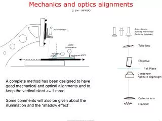
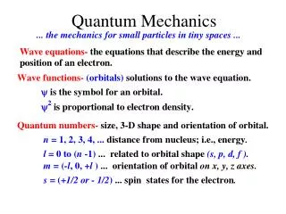
Laser Optics and Quantum Mechanics. Jason Goff, UCORE Summer ‘07 Steck Lab, University of Oregon Oregon Center for Optics. Overall Goals . Currently, the table is being tuned to allow for dipole operation. However, the Magneto-Optical Trap (MOT) is operating as designed.

E N D
Laser Optics and Quantum Mechanics Jason Goff, UCORE Summer ‘07 Steck Lab, University of Oregon Oregon Center for Optics
Overall Goals • Currently, the table is being tuned to allow for dipole operation. However, the Magneto-Optical Trap (MOT) is operating as designed. • Short term goals would include a one-way barrier • Long term goals include Quantum feedback control, measurement, Chaos, and Quantum to classical transitions
Table Lay-out • The table is arranged with a MOT and a dipole trap. Of the two, the MOT is the one that has a magnetic coil assembly. Visible “MOT” in Hellma Cell with AH coils visible above and below the cell assembly (courtesy of Steck Lab).
Quantum Mechanisms • MOT • Considered by the communitee to be the general workhorse for quantum experimentation. • Uses 6 lasers with optics to create a focus in the center of Hellma Cell. These beams can be emitted by multiple lasers or by one laser and split via a beam splitter. • In tandem to the lasers are two coils called AntiHelmholtz Coils. These work in concert to ensure that the 87Rb is collected in the center of the Hellma cell for sampling and testing. • Not as effective as a dipole trap for experimental testing Courtesy of Steck Lab
MOT arrangement • These pictures demonstrate the arrangement of the MOT assembly; the circles being the AH coil, the 6 red arrows signifying the laser beam trajectory to the center, and then the blue dot which signifies the trapped element (in this case, 87Rb).
AH Driver Board • An Anti-Helmholtz driver board completely “stuffed” and ready to use. • Has two different voltage circuits, a 15V circuit for running the board and a 40V circuit for running the coils. • Boards are designed to run a single coil and operate in tandem as a Master-Slave system. • The master board controls the current control to the coils while the slave control adjusts the gain of the slave coil, i.e. the difference current through each coil. • The optimal gain is 1:1 Pictures courtesy of Jeremy thorn
UCORE Contribution • Upon arrival in to the Steck lab, I was assigned the task of diagnosing a laser voltage supply board. However, due to the enormous task and my lack of experience, it was decided that I should build and test Anti-Helmholtz driver boards. • This task would give me the necessary skills to understand future projects which might need electronics or a circuit background. • UCORE made possible the construction of 3 separate boards as well as other minor equipment additions.
Sources and Acknowledgements • Pictures courtesy of Steck lab, University of Oregon • Thanks to Dan Steck, University of Oregon • Phillips, William D. (1998): Laser cooling and trapping of neutral atoms, in: Reviews of Modern Physics 3 / 70, S. 721-741. • Steck, Daniel A (2006): Classical and Modern Optics, Class Notes, pg 207-227. Research made possible by grants from the NSF and UCORE