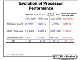
Performance Analysis of Processor
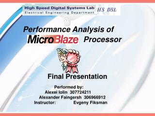
Performance Analysis of Processor. Final Presentation. Performed by: Alexei Iolin 307724211 Alexander Faingersh 306966912 Instructor: Evgeny Fiksman. Agenda. Project Goals MicroBlaze architecture

Performance Analysis of Processor
E N D
Presentation Transcript
Performance Analysis of Processor Final Presentation Performed by: Alexei Iolin 307724211 Alexander Faingersh 306966912 Instructor: Evgeny Fiksman
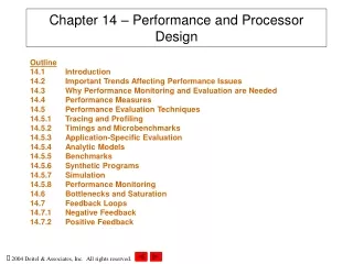
Agenda • Project Goals • MicroBlaze architecture • OPB timer/counter and interrupt controller • Connecting Customized IP to FSL bus • Our Customized IP • Time performance measurements • Current measurements • Conclusions
ProjectGoals MicroBlaze is a Soft core Processor developed by Xilinx that meets performance, area-efficiency and low cost targets. Although using the MicroBlaze enables fast system development on a single FPGA, some of the “special” applications run slower than in Hardware IP. We will examine this with EDK environment • Examination of MicroBlaze calculation abilities by measuring time of running applications and examining Interrupt handler abilities. • Measuring power consumption by sampling current during program executions. • Implementing arbitrary application in Hardware (IDCT) and using it as a hardware acceleration for MicroBlaze. • Implementing the same functionality in C and comparing the results with hardware. • Adding self written C code for testing FPU.
EDK andMicroBlaze • The Embedded Development Kit (EDK) is a set of microprocessor design tool and common software platforms. The EDK includes the Platform Studio tool suite, the MicroBlaze core and a library of peripheral IP cores. • The MicroBlaze embedded soft core is a 32-bit Reduced Instruction Set Computer (RISC) optimized for implementation in FPGA. Operating at up to 200 MHz. • MicroBlaze enables to have complete flexibility in setting peripherals, memory and interface features on a single FPGA
MicroBlaze Hardware Options and Functions • Hardware Barrel Shifter • Hardware Divider • Machine Status Set and Clear Instructions • Hardware Exception Support • Pattern Compare Instructions • Floating-Point Unit (FPU) • Hardware Multiplier Enable Bus Infrastructure • Data-side On-chip PeripheralBus (DOPB) • Instruction-side On-chip Peripheral Bus (IOPB) • Data-side Local Memory Bus(DLMB) • Instruction-side Local Memory Bus (ILMB) • Fast Simplex Link (FSL) MicroBlaze Architecture
OPB Timer/Counter The TC (Timer/Counter) is a 32-bit timer module that attaches to the OPB. • Two programmable interval timers with interrupt, event generation, and event capture capabilities. • Each timer has 3 32bit registers: • 1. TCSR - Control Register • 2. TLR - Load Register • 3. TCR - Counter Register • Both timer/counter modules can be used in a Generate Mode, a Capture Mode, or a Pulse Width Modulation (PWM) Mode.
Continuing INTC… INTC Features • Priority between interrupt requests is determined by vector position. • Supports data bus widths of 8-bits, 16-bits, or 32-bits for OPB interface. • Number of interrupt inputs configurable up to the width of data bus. • Interrupt Enable Register (IER) for selectively disabling individual interrupt inputs. • Master Enable Register for disabling interrupt request output and choosing software or hardware interrupts. • Each input is configurable for edge or level sensitivity.
Connecting Customized IP to FSL BUS • MicroBlaze has the ability to use its dedicated FSL bus interface to integrate a customized IP core into a MicroBlaze soft processor-based system. • Generally, there are two ways to integrate a customized IP core into a MicroBlaze • One way is to connect the IP on the (OPB) . 2. The second way is to connect the user IP to the MicroBlaze dedicated Fast Simplex Link (FSL) bus system. • If the application is time-critical, the designer should take bus standard delays into account, thus the user IP should be connected to the FSL bus system. Otherwise, it can be connected as a slave or master on the OPB.
Continuing Our Customized IP… The whole embedded system consists of the MicroBlaze itself, two FSL bus systems, the user core, an OPB on-chip bus, two OPB peripherals (UART lite ,Timer and Interrupt Controller) and the on-chip block RAM. The application program is stored in the on-chip block RAM.
It is possible to use more than 2 dynamic inputs and more than 1 output because up to 16 FSL interface busses are provided. • User IP is independent, doesn’t affect the internal MB RISC architecture thus won’t decrease the clock frequency of MB. • Outside implementation of IP allows to run customs calculations parallel to main stream application. • The new hardware doesn't require inline assembler code because the FSL interface has predefined C-macros for I/O to IP
Our Customized IP • We connected 1-dimension IDCT HW block on specially configured FSL . • A 1-dimension IDCT realized in software requires a high execution time because the C- program executes many loops sequentially . • Implementation of application as hardware module greatly reduces the execution time due to parallel processing. • The software application writes 8 values from memory to the FSL. The IDCT core gets the data, calculates the result and returns the result data (8 words) back to MB trough the FSL. • The HW implementation of IDCT is written in VHDL (the code is available in EDK IP wizard
Time measurements • The time measurement relies on accessing the Timer/Counter MB OPB peripheral and controlling Timer's counting registers. • The counter I set to count CPU clocks during the program execution periods. • Time is calculated from counter value and the system clock frequency. • Measurement result for example: We can see that the time is T=9366019 clocks. The MB frequency is 100MHz. Thus the time is T= 9366019/100exp(+6) = 93.66 msec.
Interrupt controller time measurements • Measure the clean program time (T) • 2. Load the Time register with A=0XFFFFFFFF- T+ 0XFF • 3. Measure the final time including INTC (T1) • 4. Delta = T1- (A+FF)
Current measurements The current measurement relies on connecting power resistor serially to MB 1.5v power block and recording the voltage on the resistor by sampling with NI DAC Labview system.The program repeated for 5000 times for better statistics. SampleFreq=20KHz. For example:
Conclusions • MicroBlaze is a very effective solution for easily configurable systems demands. • Distinguishing critical passes and implementing them in HW can greatly decrease execution time. • FSL is the most effective (energy and time) way for connecting HW acceleration to MB. • FPU is the most problematic consumer. Massive use of FPU is not recommended in MB. • Interrupts input frequency is maximum 890kHz.