HV current limit GUI
200 likes | 232 Vues
HV current limit GUI. Start the HV current limit GUI using the « GUI starter » GUI, Page B, button 4 (to start the GUI starter, type in a terminal window: cd; setup d0online; ./startguis.py). write HV pod name here. click here to get the current limits. click here to increase the

HV current limit GUI
E N D
Presentation Transcript
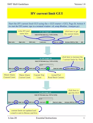
HV current limit GUI Start the HV current limit GUI using the « GUI starter » GUI, Page B, button 4 (to start the GUI starter, type in a terminal window: cd; setup d0online; ./startguis.py) write HV pod name here click here to get the current limits click here to increase the 3 current limits by 10uA Minor Alarm Current Limit Major Alarm Current Limit Current Trip Limit Actual Pod Read Back Current click here to quit the GUI current limits are updated and a mail is sent to Breese and Eric Essential Instructions
L6 L9 F8 p-side p-side p-side F6 L9 L6 n-side n-side n-side H6 L3 D0SMT detector types Essential Instructions
Muon wall NW SW West Cathedral 120 ladders 72 F-wedges 48 H-wedges ADAPTER CARDS SW1 NW0 NW1 SW0 F12 F11 F10 F9 F8 F7 F6 F5 F4 F3 F2 F1 H4 H3 H2 H1 L.M. CABLE Calo South End Cap Muon wall B5 B6 B3 B4 B1 B2 Calo North End Cap Muon wall CFT Central Calo NE0 NE1 SE1 SE0 80/3M CABLE INTERFACE BOARD CRATES NE SE East Cathedral Muon wall Essential Instructions
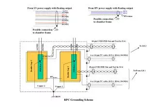
PwrPC PwrPC PwrPC 1 5 5 3 HV mod I,V,T Monitoring 1553 Monitoring HV breakout box 17 twisted pair cables I B SEQ VME Crates (4x3) MCH3 25’ High Mass Cable (3M/50 conductor) Platform HV Sequencer Crates (6x20) Interface Board Crates (8x18) SEQ Controller HV fanout 1=>4 Cathedral LV 25 twisted pair cables Fuse Panel ~19’-30’ High Mass Cable (3M/80 conductor) CLKs PowerPCs and Single Board Computers are accessed thru Ethernet Cathedral MCH2 Optical Link 1Gb/s HV Crates (8x6+2x4) Bulk LV Power Supplies Adaptor card Horse Shoe 8’ Low Mass Cables CLKs CLKs VRBC PDAQ (L3) VRB MCH2 VTM 3/6/8/9 Chip HDI S B C Sensor Serial Command Link Around Iteraction Region 3/6/8/9 Chip HDI Sensor VRB Crates (12x10) Monitoring SDAQ
connection silicon strip R/O chip to input preamp LV +HV -HV LV HDI AVDD SVX AVDD2 DVDD sensor +HV switches n-side coupling capacitors polysilicon resistors - HV p-side DATA n+ strips side buffer p+ strips side SVX Interface Board SVXIIe HDI silicon sensor HDI SVXIIe About LV and HV (1) • Our silicon detectors are made of 1 or 2 silicon sensor(s) glued to an HDI which carries • SVXIIe chips. These chips allow to read out information about the charge collected on the • sensor strips, when charged particles went through the sensor(s). For the detector to • function properly: • the silicon sensors must be depleted. This requires 1 (single sided sensors) or 2 (double-sided sensors) HV power supplies. • the SVXIIe read out chips must be powered. This requires 3 different LV power supplies: AVDD, AVDD2, and DVDD. • HV and LV are provided by the IB to the HDI which, in turn, provides it to the sensor(s) and • to the SVXIIe chips, respectively. Essential Instructions
B F D H G A E C Coolant Flow SMT cooling system Cryo Permit Coolant IN/OUT Temp Drip Temps of selected devices Water Flow Hygrometry SHV cable Smoke (HSSO) 24 SHV inputs HV Fan Out box (MCH2) 7 HV Power Supply (MCH2) RMI/RM (cathedral) Control/ Status 50 cond Air Flow 0 Power Supply (cathedral) Water Flow Drip HV Break Out box (platform) 12 cond Smoke FusePanel (cathedral) RMI/RM (platform) Control/ Status AVDD AVDD2 DVDD VCC +15V Power Supply (platform) Ladder 34 cond (8HVs + 1 temp) Chain B CLK/CLKB +HVA +5V -5V Low Mass Cables 80 cond -HVA dvdd SEQuencer (platform) CLK/CLKB avdd2 Adaptor Card (Horse Shoe) Chain A avdd ON/OFF hdi A enable 50 cond 0-1 buffer A enable Ladder FPGA monitoring chan. A: AVDD AVDD2 DVDD Temp 2-3 trip A 4-5 data/control lines Optical Fiber 6-7 Interface Board (cathedral) details given for chan. A only same for other 7 channels 0 1 2 3 4 5 6 7 0 VTM (MCH2) 1 VRB (MCH2) 2 3 Essential Instructions
IB switches AVDD AVDD2 DVDD +HV on LV 200P B5-7-4 on on HV pods on -HV B5-7-5 201N on on LV power supplies B5-8-5 on on B5-8-6 off off HDIs Interface Board About LV and HV (3) General rule for HDI(s): Turn ON LV first, then HV. Turn OFF HV first, then LV. HV +/- switches AVDD/AVDD2/DVDD switches Essential Instructions
SVXIIe read out chips download parameters you should redownload all the crates with these default parameters at the beginning of each shot setup, to make sure the SVX chips are properly initialized for Physics! Essential Instructions
High DVDD currents and HDI LV Trips (1) If a lot of HDIs show high currents in the DVDD Current GUI, that usually means that the SVX chips are not read out. This happens when the crates are not in a global run, or when the global run is pause or stalled for some reason. You should not let the system in that state for too long. DVDD Currents GUI color coding: orange: LV is OFF green: LV is ON and I_DVDD OK purple: LV is ON and I_DVDD slightly high red: LV is ON and I_DVDD high red/black: Abnormal state (Trip or Buffer Disabled) grey: Channel permanently disabled or not used Essential Instructions
Pulses are OFF Pulses are ON Pulses are OFF High DVDD currents and HDI LV Trips (2) • A way to lower the DVDD current drawn by the SVX chip, is to send trigger to the Sequencer Controllers so as to make the chips work. This can be achieved in several ways, by: • having the crates in a working Global Run, • having the crates out of the Global Run and making use of a special run which just sends triggers to the sequencer crates (the VRB crates are not read out). This is described in the « SMT Crater » section, • sending triggers to the Sequencer Controllers via the 1553, by pressing the « turn pulses ON » button in the SMT Download GUI main page. Do not forget to « turn the pulses OFF » before the Global Run starts or resumes readout of the SMT crates. If you try to read out the crates while pulses are ON, this will result in 100% L1 FEB, because you are sending more triggers to the sequencer crates than to the VRB crates. Essential Instructions
130 253 125 High DVDD currents and HDI LV Trips (3) If some HDIs consistently draw too much current (red or purple on the DVDD Currents GUI) you need to REDOWNLOAD them. The first step is to find what VRB they are connected to. This can be done looking at the IB mapping chart: Essential Instructions
High DVDD currents and HDI LV Trips (4) Then, go to the corresponding VRB in the SMT Download GUI, and click download on the Left-click menu of the corresponding sequencer. Most buttons have a Right- and Left-click menus. A Left-click on an item of a menu executes that item A Right-click on a menu closes it. If the download was successful, the HDIs should appear green, both in the Download GUI and on the DVDD Currents GUI: Essential Instructions
B3-L4-HDI04-(N) B3-L4-HDI04-(N) High DVDD currents and HDI LV Trips (5) If one or more HDIs appear red in the Download GUI, the download was not successful. Interface Board Sequencer VRB • HDI Status Color Coding: • white: permanently disabled • yellow: disabled • grey: enabled and either OFF or unknown • green: enabled, ON and downloaded OK • red: enabled, (ON and failed download) or tripped Sequencer Fibers VRB Fibers • IB Channel Status • Color Coding: • green: OK • red: tripped 1 Fiber = 2 HDIs Try to download a few more times at the Sequencer level. If it still does not work, try to download at the corresponding Sequencer Fiber level. Essential Instructions
130 3 125 B3-L4-HDI04-(N) B High DVDD currents and HDI LV Trips (6) 1. If this still does not work, it sometimes helps, when an HDI is reluctant in downloading properly, to turn it OFF and ON again. 2. In the same way, if an HDI has tripped, to recover it, you need to clear the trip by turning the HDI OFF and then turn it back ON again, by downloading it. TRIP In both cases, if the High Voltage is ON, you will need first, to RAMP DOWN and TURN OFF the HV on ALL HDIs connected to the SAME SEQUENCER as the HDI you want to turn ON or OFF. Otherwise, the Download GUI will not execute your commands. Essential Instructions
B3-L4-HDI04-(N) B3-L4-HDI04-(N) B B High DVDD currents and HDI LV Trips (6) In the left-click menu of each Interface Board connected to the sequencer, the corresponding HDI(s) is(are) connected to, click on « start HV GUI ». For each IB a GUI will pop up showing the pods you need to ramp down and turn off. In our example, HDI B3-L4-HDI04 is connected to sequencer SEQ_030B14. That sequencer is connected to 2 IBs, namely: INT_NW_0B0E and INT_NW_0B10. Start the HV GUI for the first IB: Do the same for the second IB: In all the HV GUIs, do « Unlock », « Set HV to 0% », « Ramp », and when the all the « V_Read » values are below 3V, click on « Off ». You are now ready to take care of the problematic HDI. Essential Instructions
130 3 125 B3-L4-HDI04-(N) B High DVDD currents and HDI LV Trips (7) Turn OFF the tripped HDI: B3-L4-HDI04-(N) OFF As explained earlier, try to download the HDI at the sequencer level or at the Sequencer Fiber level. If the download worked, in the HV GUIs shown in the previous page, turn the HV ON, « Set HV->100% », « Ramp ». Once the target voltages are reached, « Lock », « File->Quit », and you are done! If not, you need to turn the HDI off, disable it as explained in the next page ... Essential Instructions
Monitoring (1) Monitoring of the data quality is done at the strip level in processes which run in the VRB crates Power PCs (IOCs). The status of these IOCs can be looked at from the « Readout IOC Monitor » (from GUI starter, page C, button 6). Power PCs (IOCs) in the 12 VRB crates CPU consumption varies between 50 and 75% when monitoring is running For each VRB crate, the monitoring process captures events from the SBC and makes histograms out of them. A Linux box queries the IOCs one after the other to get their histograms out, so as to allow their browsing through a WEB interface. When an IOC is queried, if the number of events accumulated by the IOC lies between 8,000 and 10,000, an update will be sent for the corresponding crate to the Significant Event System (the result of which is shown in the Alarm Display) for major alarms related to the « Occupancy » and « Dead » categories. An « Occupancy » alarm is set whenever the occupancy of an HDI is greater than 35%. A « Dead » alarm is set if (a) chip(s) of an HDI never appear in the read out stream. Note that disabled HDIs do not generate a « Dead » alarm. You have to take Occupancy and Dead alarms seriously! Essential Instructions
Monitoring (2) You can connect with Netscape (or you favorite Browser) to the Monitoring Server page (http://www-d0ol/smtMonitoring/). It also appears labeled as « SMT Monitoring Page » in the Netscape Toolbar and in the Bookmarks menu. click on this to update the page VRB crates Last time data were received from IOC in VRB crate 62 Last time update was sent to SES (Alarm system) for crate 65 As a general rule, the monitoring should always be turned on during Global Runs (zero_bias or physics). Check this by looking at the IOC CPU consumption, on theReadout IOC Monitor GUI, at the « IOC DATA UPDATE TIME » and « SES UPDATE TIME » on the Monitoring WEB page. The monitoring is started at the beginning of a run and stopped at the end of a run. If monitoring does not seem to be on, during a Global Run, check with the DAQ shifter that the trigger file has SMT monitoring enabled. If not, the DAQ shifter should enable the monitoring and start a new run. You can also start the monitoring « by hand », VRB crate by VRB crate, usingthe crate « details » page in the SMT download GUI, as follows: Essential Instructions
Monitoring (3) Imagine that for some reason, you need to power cycle crate 66 during a global run. After pausing the run, you cycle the power on crate 66, you wait for the Power PC to reboot, you « Reinit VME » and you resume the run. Now, what you see on the IOC monitoring is that the monitoring process in crate 66 is probably not processing anything: open the details page for crate 66 in the SMT download GUI and click on the « Start monit run » item in Left-clickmenu of the VRBCR_66 button. In the resulting pop up window, write the current run number and click « Start » You can open a terminal window on the IOC by connecting to it through the MCH2 terminal server. The login name is: ioc the passwd: 0nlined0 Essential Instructions
Monitoring (4) If everythig goes as expected, this is what you should then see: After 5 to 10 minutes, you can also check that the « IOC DATA UPDATE TIME » and « SES UPDATE TIME » are current on the Monitoring WEB interface. Essential Instructions