Download

1 / 28
290 likes | 450 Vues
Flywheel Storage for Lunar Colonization. University of Idaho Department of Electrical and Computer Engineering. Purpose Statement.

E N D
Flywheel Storage for Lunar Colonization University of Idaho Department of Electrical and Computer Engineering
Purpose Statement To establish the scientific and technical merit, and feasibility, of using flywheel energy storage systems in support of human colonization and exploration of the lunar surface
Flywheel Storage for Lunar Colonization • Machine Topology Evaluation • Power Electronics and Control • Construction of Test Apparatus
Flywheel Storage for Lunar Colonization Machine Topology Evaluation Ian Higginson
Research Objectives • Evaluate technical merit and feasibility of: • Electrical energy transfer machinery that minimizes iron idling losses • Extreme temperature electronics to manage energy transfer and storage
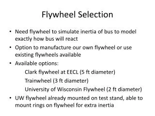
Flywheel Criteria • No slip rings/commutators • Significant idling iron loss reduction • Low volume • High torque per volume • High torque per mass
Machine Topologies • Synchronous Reluctance • Field Regulated Reluctance • Iron-on-rotor PM; • Ironless stator • Iron rotor • Ironless PM (Halbach array)
Torque per Unit Volume • Synchronous Reluctance: 34.16 kNm/m3 • Field Regulated: 35.52 kNm/m3 • Iron-on-rotor PM: 27.18 kNm/m3 • Ironless PM: 25.33 kNm/m3
Goals • Prepare Phase 2 Proposal • Formalize force density equations • Verify analytical data • Prototype low idle iron loss machine • Develop equations for torque per unit mass
Power Electronics for Lunar Flywheels Power Electronics and Control Christopher Douglas
Research Objectives • Evaluate technical merit and feasibility of: • Electrical energy transfer machinery that minimizes iron idling losses • Extreme temperature electronics to manage energy transfer and storage
Purposes • Operate over extreme temperature range • Reduce excess mass • Increase energy/power density • Develop control method for flywheel
Lunar Environment • Extreme thermal & radiation environment • Phase I involves thermal problems • -190C to +125C • 336 hours of Lunar night/day • Radiation exposure • Heat transfer mechanisms • Conduction • Radiation
Semiconductor Technologies • Silicon on Insulator • Commercial Ratings HTANFET • 90V, 1A • Rated -55C to +225C • Cycle Testing -195C to +85C • Silicon Germanium HBT – Research Data • 50V, 2A • Cycle Testing -195C to 25C • Cycle Testing 25C to 300C
Application • Heated or cooled enclosure • Added mass • Lost energy • Temperature division multiplexing (TDM) • Range dependent electronics • Strategic layout of electronics • Stacked MOSFET topology
Deflux Control • Rotor defluxing method • Decaying sinusoidal current (θr) • Parameters • Decay rates • Frequency of defluxing current
Future Goals • Prepare phase II proposal • Acquire models for power electronics • Develop control system for lab prototype • Deflux spinning rotor • Investigate: • Temperature division multiplexing • Stacked MOSFET topology • Heat transfer in vacuum
The University of Idaho Construction of Test Apparatus Timothy Hildebrandt, Bryan Hyde, Josh Ulrich, Kord Hubbard
Synchronous Reluctance Machine • Purchase Machine • High Quality Bearings • Controlled Environment • Characterize Losses • Low Friction Machine • Power Electronics • Lunar Environment • Adaptability to Machine
Power Loss Characterization • Present: • Armature resistance • Brush drop losses • Interpole winding resistance • Future: • Iron losses • Difficult to measure
Preliminary Iron Losses • Constant Speed • Vary Gen. Field Current
Power Inverter • Used for defluxing
Future Goals • Prepare for Phase II Proposal • Purchase/Characterize machine • Develop testing strategy • Measure iron losses accurately • Define lunar power requirements
2010 Timeline for Future Work • April – Sep.: Prepare Phase 2 Proposal • April 30th: Formalize force density equations • May 1st: Begin verification of analytical data • May 15th: Parameterize defluxing method • May – Aug: Investigate TDM scheme • June 1st: Construct flywheel prototype
2010 Timeline for Future Work • June: Construct prototype electronics system • June – July: Develop testing strategies • June – Aug: Collect data at Boeing • June – Aug: Characterize machine • June – Sept: Investigate switch device models • June – Aug: Develop torque per mass eq’s.
2010 Timeline for Future Work • Aug: Prepare testing environment • Aug: Design of power electronic system • Aug – Sept: Document results • Sept: Submit Phase 2 Proposal • Sept: Measure losses accurately
The University of Idaho Discussion