Flywheel
DOM<br>DYNAMICS OF MACHINES<br>UNIT 1


Flywheel
E N D
Presentation Transcript
The turning moment diagram for a petrol engine is drawn to the following scales : Turning moment, 1 mm = 5 N-m ; crank angle, 1 mm = 1°. The turning moment diagram repeats itself at every half revolution of the engine and the areas above and below the mean turning moment line taken in order are 295, 685, 40, 340, 960, 270 mm2. The rotating parts are equivalentto a mass of 36 kg at a radius of gyration of 150 mm. Determine the coefficient of fluctuation of speed when the engine runs at 1800 r.p.m.
Given • m = 36kg, • k= 150 mm, • N = 1800 rpm • 1 mm ‘T’ = 5Nm • 1 mm ‘q’ = 1o • 1 mm2 = 5 x p/180 = 0.0872 N-m
We need the maximum fluctuation of energy to find Cs => DE is found from the turning moment diagram
A shaft fitted with a flywheel rotates at 250 r.p.m. and drives a machine. The torque of machine varies in a cyclic manner over a period of 3 revolutions. The torque rises from 750 N-m to 3000 N-m uniformly during ½ revolution and remains constant for the following revolution. It then falls uniformly to 750 N-m during the next ½ revolution and remains constant for one revolution, the cycle being repeated thereafter. • Determine the power required to drive the machine and percentage fluctuation in speed, if the driving torque applied to the shaft is constant and the mass of the flywheel is 500 kg with radius of gyration of 600 mm.
Given N = 250 rpm i.ew = 2pN/60 = 26.18 rad/s Rev. = 3 i.e. q = 6p m = 500 kg k = 600 mm = 0.6m
From the turning moment diagram, Work done = Area under curve . = OAEF+ABG + BGHC + CHD = 6p x 750 + ½ x p x 2250 + 2p x 2250 + ½x px 2250 = 11250 p N-m But, the work done can also be taken as, Work done = Tmean x 6p Tmean = 11250p / 6p = 1875N-m Power = Tmean x w = 1875 x 26.18 Power = 49.125 kW
Find area above the Tmean line. • Energy, DE= BLM + BMNC + CNP • We need LM and NP • Consider similar triangles, • LM= 0.5p • For finding NP • NP = 0.5p • Energy, DE= ½ x0.5px1125 + 2p x 1125 • + ½x 0.5p x 1125 • DE= 8837 N-m
The turning moment curve for an engine is represented by the equation,T = (20 000 + 9500 sin 2θ – 5700 cos 2θ) N-m, where θ is the angle moved by the crank from inner dead centre. If the resisting torque is constant, find: • 1. Powerr developed by the engine ; 2. Moment of inertia of flywheel in kg-m2, if the total fluctuation of speed is not exceed 1% of mean speed which is 180 r.p.m; and 3. Angular accelerationof the flywheel when the crank has turned through 45° from inner dead centre.
Given : T = (20 000 + 9500 sin 2θ – 5700 cos 2θ) N-m ; N = 180 r.p.m. or ω = 2π × 180/60 = 18.85 rad/s TMD
Work done per revolution Tmean= Work / q = 40000p/2p =20000 N-m Power = Tmean x q = 20000 x 18.85 Power = 377 kW
The turning moment diagram for one stroke (i.e. half revolution of the crankshaft) is shown. Since at points B and D, the torque exerted on the crankshaft is equal to the mean resisting torque on the flywheel
Maximum fluctuation of energy • But, Maximum fluctuation of energy can also be written as, DE = Iw2Cs 11078 = I x (18.85)2 x 0.01 I = 3121 kg-m2
Angular acceleration at 45 degree • Excess torque at 45 degree • Excess torque at 45 degree can also be written as Tmean = I x a a = 9500/3151 = 3.044rad/s2
The turning moment diagram for a multicylinder engine has been drawn to a scale 1 mm = 600 N-m vertically and 1 mm = 3° horizontally. The intercepted areas between theoutput torque curve and the mean resistance line, taken in order from one end, are as follows : • + 52, – 124, + 92, – 140, + 85, – 72 and + 107 mm2, when the engine is running at a speed of 600 r.p.m. If the total fluctuation of speed is not to exceed ± 1.5% of the mean, find the necessarymass of the flywheel of radius 0.5 m
A three cylinder single acting engine has its cranks set equally at 120° and it runs at 600 r.p.m. The torque-crank angle diagram for each cycle is a triangle for the power stroke with a maximum torque of 90 N-m at 60° from dead centre of corresponding crank. The torque on the return stroke is sensibly zero. Determine : 1. power developed. 2. coefficient of fluctuation of speed,if the mass of the flywheel is 12 kg and has a radius of gyration of 80 mm, 3. coefficient of fluctuationof energy, and 4. maximum angular acceleration of the flywheel.
Given N = 600 r.p.m. ω = 2 π × 600/60 = 62.84 rad /s; Tmax = 90 N-m; m = 12 kg; k = 80 mm = 0.08 m TMD
Work done/cycle (Area under curve) • 3 x (Area of triangle) • 3 x ½ x p x 90 = 424 N-m • Tmean = Work / q = 424 / 2p = 67.5 N-m • Tmean = (Tmax + Tmin)/2 Tmin= 2 x Tmean – Tmax Tmin= 45 N-m • The turning moment diagram can be represented as,
Fluctuation in energy • Maximum = E + 5.89 • Minimum = E-5.89 • Maximum fluctuation in energy DE = E + 5.89 – (E – 5.89) = 11.78 N-m
Coefficient of fluctuation of energy • Maximum angular acceleration of flywheel • Flywheel reaches maximum acceleration when maximum energy is available • Maximum energy is available when the difference between maximum torque available and the torque needed for operation is maximum. • That is,. when the torque is at Tmax, energy to flywheel is Tmax - Tmean
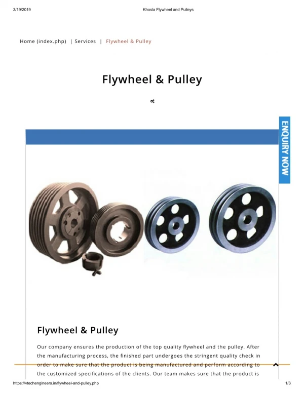
Dimensions of the Flywheel Rim Consider a rim of the flywheel as shown. • Let D = Mean diameter of rim in metres, • R = Mean radius of rim in metres, • A = Cross-sectional area of rim in m2, • ρ = Density of rim material in kg/m3, • N = Speed of the flywheel in r.p.m., • ω = Angular velocity of the flywheel in rad/s, • v = Linear velocity at the mean radius in m/s = ω .R = π D.N/60, and • σ = Tensile stress or hoop stress in N/m2 due to the centrifugal force.
Formula to remember • Centrifugal / Hoop stress. s = r x v2 • linear Velocity ,. v = kw or Rw
Dimensions of the Flywheel Rim Consider a rim of the flywheel as shown. • Let D = Mean diameter of rim in metres, • R = Mean radius of rim in metres, • A = Cross-sectional area of rim in m2, • ρ = Density of rim material in kg/m3, • N = Speed of the flywheel in r.p.m., • ω = Angular velocity of the flywheel in rad/s, • v = Linear velocity at the mean radius in m/s = ω .R = π D.N/60, and • σ = Tensile stress or hoop stress in N/m2 . due to the centrifugal force.
Formula to remember • Centrifugal / Hoop stress. s = r x v2 • linear Velocity ,. v = kw or Rw = pDN/60 • Coefficient of energy, CE = DE/Work done • Volume of Rim ,. VOLUME = pDA • m = Volume × density = π D.A.ρ • σ = ρ.R2.ω2 = ρ.v2 ....(∵ v = ω.R)
The turning moment diagram for a multi-cylinder engine has been drawn to a scale of 1 mm to 500 N-m torque and 1 mm to 6° of crank displacement. The intercepted areasbetween output torque curve and mean resistance line taken in order from one end, in sq. mm are– 30, + 410, – 280, + 320, – 330, + 250, – 360, + 280, – 260 sq. mm, when the engine is running at 800 r.p.m.The engine has a stroke of 300 mm and the fluctuation of speed is not to exceed ± 2% of the mean speed.Determine a suitable diameter and cross-section of the flywheel rim for a limiting value of the safe centrifugal stress of 7 Mpa. The material density may be assumed as 7200 kg/m3. The width of the rim is to be 5 times the thickness.
Given N = 800 r.p.m. or ω = 2π × 800 / 60 = 83.8 rad/s; Stroke = 300 mm ; σ = 7 MPa = 7 × 10⁶ N/m2 ; ρ = 7200 kg/m3 Cs = ± 2% = 4% = 0.04
Diameter of the flywheel rim Let D = Diameter of the flywheel rim in metres, and v = Peripheral velocity of the flywheel rim in m/s. We know that centrifugal stress (σ), 7 × 106 = ρ.v2 = 7200 v2 v2= 7 × 10⁶/7200 = 972.2 ∴ v = 31.2 m/s But, v = π D.N/60 ∴ D = v × 60 / π N = 31.2 × 60/π × 800 D = 0.745 m
Cross-section of the flywheel rim Let t = Thickness of the flywheel rim b = Width of the flywheel rim = 5 t …(Given) ∴ Cross-sectional area of rim, A = b.t = 5 t × t = 5 t 2 • Turning moment diagram- Scale • turning moment scale is 1 mm = 500 N-m and • crank angle scale is 1 mm = 6° = π /30 rad, Therefore • 1 mm2 on the turning moment diagram = 500 × π / 30 = 52.37 N-m
Energy Variation • Mass of flywheel
Dimensions of Flywheel We know that mass of the flywheel rim (m), m = Volume × density = π D.A.ρ 604 = π × 0.745 × 5t2 × 7200 = 84 268 t 2 ∴ t2 = 604 / 84 268 = 0.007 17 m2 t = 0.085 m = 85 mm and b = 5t = 5 × 85 b = 425 mm
A machine punching 38 mm holes in 32 mm thick plate requires 7 N-m of energy per sq. mm of sheared area, and punches one hole in every 10 seconds. Calculate the power of the motor required. The mean speed of the flywheel is 25 metres per second. The punch has a stroke of 100 mm. Find the mass of the flywheel required, if the total fluctuation of speed is not to exceed 3% of the mean speed. Assume that the motor supplies energy to the machine at uniform rate.