Download

1 / 18
200 likes | 295 Vues
A Presentation On Flywheel. Hanish -243/C/10 Gurmeet Singh-242/C/10 Gaurav Rana- 241/C/10 Digvijay-240/C/10. AIM. To determine the moment of inertia of a flywheel about its own axis of rotation. Apparatus. The flywheel, weight box, thread, stop-watch, metre scale and vernier calipers.

E N D
A Presentation On Flywheel Hanish -243/C/10 Gurmeet Singh-242/C/10 Gaurav Rana- 241/C/10 Digvijay-240/C/10
AIM To determine the moment of inertia of a flywheel about its own axis of rotation.
Apparatus The flywheel, weight box, thread, stop-watch, metre scale and vernier calipers.
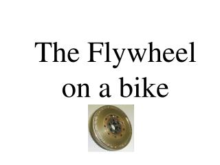
Description of Apparatus • Flywheel is simply a heavy wheel with a long axle which when properly supported in bearings may remain at rest in any position, i.e., its centre of gravity lies on the axis of rotation. • Its moment of inertia can be determined experimentally by setting it in motion with a known amount of energy.
Theory • The flywheel is mounted in its bearings with its axle horizontal and at a suitable height from the ground. • A string carrying a suitable mass m at its one end and having a length less than the height of the axle from the ground, is wrapped completely and evenly round the axle. • When the mass m is released, the string unwinds itself, thus setting the flywheel in rotation.
Theory (Contd…) • As the mass descends a distance h, it loses potential energy mgh which is used up partly in • providing kinetic energy of translation (½mv2) • giving kinetic energy of rotation to the flywheel (½Iω2) • doing work against friction (n1F). Hence , mgh = ½mv2 + ½Iω2 + n1F.
Theory (Contd…) • After the mass has detached, If flywheel makes n2 rotations in this time, the work done against friction is equal to n2F and is equal to the kinetic energy of the flywheel at the instant the mass drops off. • Thus n2F = ½Iω2 . • Hence I = m(2gh/ω2-r2 ) 1+n1/n2
Theory (Contd…) • If the force of friction is steady, the motion of the flywheel is uniformly retarded and the average angular velocity during this interval is equal to ω/2. • Thus ω/2 = 2πn2/t
Method • Take a string of length less than the height of the axle from the floor. Wrap the string evenly round the axle until the projecting peg is horizontal and make a mark on the string where its contact with the axle just ceases. • Let the mass be released. Count the no. of rotations n1, the flywheel makes before the loop comes off the peg and the mass drops off. Carefully start the stopwatch at the moment the mass detaches and also continue to count the no. of rotations n2 the flywheel makes before it comes to rest.
Method (Contd…) • Stop the stopwatch when the flywheel finally comes to rest and thus determine the value of t, the interval for which the flywheel continues to rotate after the detachment of the mass. • Measure the length of the string between the loop and the mark at the other end which gives h. With the help of a vernier calipers, calculate the mean radius of the axle.
Method (Contd…) • Repeat the experiment with different masses and strings of different lengths and take at least three sets of observations, and in each set for the same value of m and h take at least three observations, calculate the mean values of n1,n2 and t. • Calculate the moment of inertia of flywheel for each set of observations separately and find out the mean value of moment of inertia of the flywheel about its axis of rotation.
Sources of error and precautions • The length of the string should be always less than the height of the axle of the flywheel. • The loop slipped over the peg should be quite loose so that when the string has unwound itself. • The string should be evenly wound on the axle, i.e., there should be no overlapping of, or a gap left between, the various coils of the string. • The winding should be stopped, when almost complete the projecting peg is horizontal. • To determine h, measure only the length of the string between the loop and the mark at the other end, where the string left the axle before the start of the flywheel.
Observation Measurement of the diameter of the axle
Observation (Contd…) Measurement of h,n1,n2 and t
Calculation • Mean corrected radius of axle = 1.05 cm • Mean Inertia ,I=(0.02+0.02+0.02+0.02)/4 =0.02 kg m2
Result The moment of inertia of the flywheel about its axils of rotation = 0.02 kg m2
Criticism of the method • The exact instant at which the mass drops off can’t be correctly found out and hence the values of n1,n2 and t can’t be determined very accurately. • The angular velocity ω of the flywheel has been calculated from the formula ω = 4πn2/t on the assumption that the force of friction remains constant while the angular velocity of the flywheel decreases from ω to zero. But as the friction is less at greater velocities, we have no justification for this assumption. • Hence for more accurate result, ω should be measured by a method in which no such assumption is made e.g. with a tuning fork.