Resistors in Series Introduction
1.6k likes | 2.21k Vues
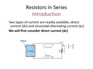
Resistors in Series Introduction. Two types of current are readily available, direct current (dc) and sinusoidal alternating current (ac) We will first consider direct current (dc). Insert Fig 5.1. Introducing the basic current flow of an electric circuit.

Resistors in Series Introduction
E N D
Presentation Transcript
Resistors in SeriesIntroduction Two types of current are readily available, direct current (dc) and sinusoidal alternating current (ac) We will first consider direct current (dc) Insert Fig 5.1
Defining the direction of conventional flow for single-source dc circuits.
Defining the polarity resulting from a conventional current I through a resistive element.
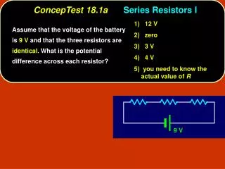
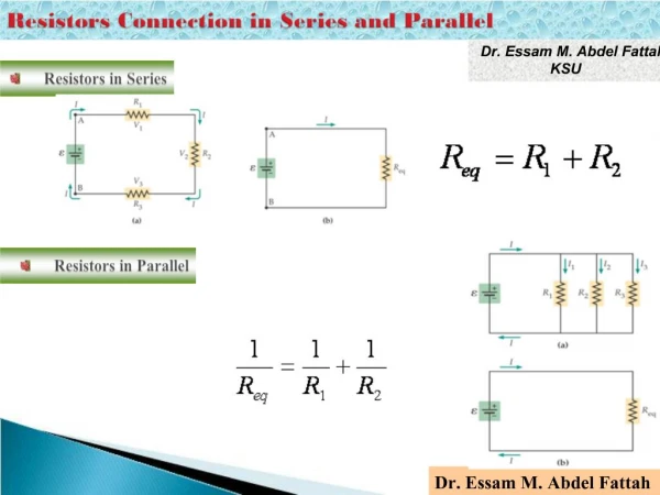
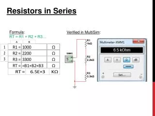
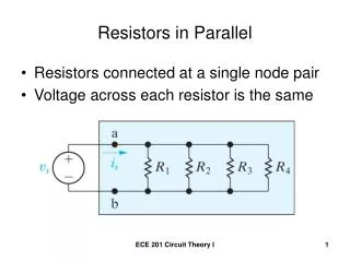
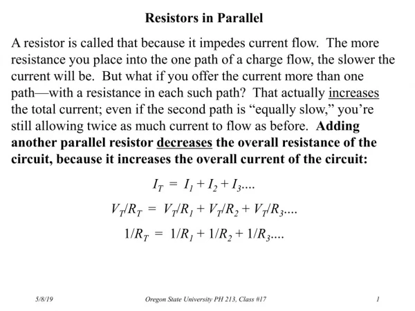
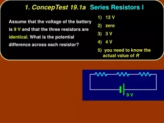
Series Resistors The total resistance of a series configuration is the sum of the resistance levels. The more resistors we add in series, the greater the resistance (no matter what their value).
Total Series Resistance • The total resistance of a series circuit is equal to the sum of the resistances of each individual series resistor
Using an ohmmeter to measure the total resistance of a series circuit.
Two series combinations of the same elements with the same total resistance.
Series Resistors • When series resistors have the same value, • Where N = the number of resistors in the string. • The total series resistance is found by multiplying the value of the same resistor times the number of resistors
Resistors in Series • A series circuit provides only one path for current between two points so that the current is the same through each series resistor
Current in a Series Circuit • The current is the same through all points in a series circuit • The current through each resistor in a series circuit is the same as the current through all the other resistors that are in series with it • Current entering any point in a series circuit is the same as the current leaving that point
Current entering any point in a series circuit is the same as the current leaving that point.
Series Circuits • Total resistance (RT) is all the source “sees.” • Once RT is known, the current drawn from the source can be determined using Ohm’s law: • Since E is fixed, the magnitude of the source current will be totally dependent on the magnitude of RT
Ohm’s Law in Series Circuits • Current through one of the series resistors is the same as the current through each of the other resistors and is the total current • If you know the total voltage and the total resistance, you can determine the total current by using: • IT = VT/RT
Ohm’s Law in Series Circuits • Current through one of the series resistors is the same as the current through each of the other resistors and is the total current • If you know the voltage drop across one of the series resistors, you can determine the current by using: I = VR/R
Notation Single-subscript notation The single-subscript notation Va specifies the voltage at point a with respect to ground (zero volts). If the voltage is less than zero volts, a negative sign must be associated with the magnitude of Va.
Notation Double-subscript notation • Because voltage is an “across” variable and exists between two points, the double-subscript notation defines differences in potential. • The double-subscript notation Vab specifies point a as the higher potential. If this is not the case, a negative sign must be associated with the magnitude of Vab. • The voltage Vab is the voltage at point (a) with respect to point (b).
Inserting the polarities across a resistor as determined by the direction of the current
Ohm’s Law in Series Circuits • If you know the total current, you can find the voltage drop across any of the series resistors by using: VR = ITR • The polarity of a voltage drop across a resistor is positive at the end of the resistor that is closest to the positive terminal of the voltage source • The resistor current is in a direction from the positive end of the resistor to the negative end
Using voltmeters to measure the voltages across the resistors
Voltage Sources in Series • When two or more voltage sources are in series, the total voltage is equal to the the algebraic sum (including polarities of the sources) of the individual source voltages
Series connection of dc supplies: (a) four 1.5 V batteries in series to establish a terminal voltage of 6 V; (b) incorrect connections for two series dc supplies; (c) correct connection of two series supplies to establish 60 V at the output terminals.
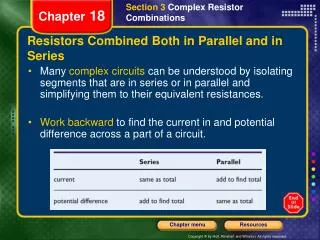
Kirchhoff’s Voltage Law The applied voltage of a series circuit equals the sum of the voltage drops across the series elements: The sum of the rises around a closed loop must equal the sum of the drops. The application of Kirchhoff’s voltage law need not follow a path that includes current-carrying elements. When applying Kirchhoff’s voltage law, be sure to concentrate on the polarities of the voltage rise or drop rather than on the type of element. Do not treat a voltage drop across a resistive element differently from a voltage drop across a source.
Kirchhoff’s Voltage Law • Kirchhoff’s voltage law (KVL) states that the algebraic sum of the potential rises and drops around a closed loop (or path) is zero.